


11
Power
The DVR’s power supply plugs into the socket marked DC 12V next to power switch (Item
number 2 in Picture 2-2). It is absolutely essential that you only use the power supply that
came with the DVR to ensure proper operation and to avoid damage.
We also recommend that you use an uninterrupted power supply (UPS) so that the system will
continue to operate in the event of a power loss. In addition, you should connect the DVR into
a UL-1449 rated surge protector. It should have a joule rating of at least 400, a response time
of 10 nanoseconds or less and a clamping voltage of no more than 330 volts.
Mouse
The included USB mouse will only operate if connected to the DVR through the USB port
on the rear of the DVR (Item number 5 in Picture 2-2). The USB port on the front of the
DVR’s screen is only for external USB storage devices.
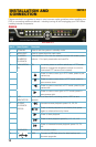
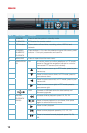
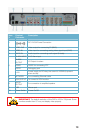
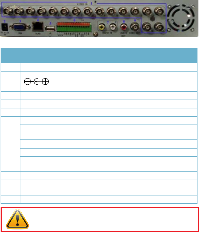
PICTURE 2-2
Item
#
Physical
Connector
Description
1 VIDEO IN Video input for connecting analog video signal input (BNC)
2
DC 12V/3A Power Connection
3 VGA OUTPUT To connect to VGA monitor
4 NETWORK For connecting Ethernet cable
5 USB Mouse port
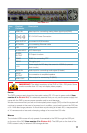
6
ALARM INPUT 8 I/O Alarm input
ALARM
OUTPUT
I/O Output for alarm
RS485 RS485 for connecting PTZ
RS232 Debugging port
+12V
Power supply for DC relay, the current is 100MA (to prevent
short circuits)
7 AUDIO IN Audio input for connecting audio signal (2 feeds)
8
AUDIO
OUTPUT
For connection to amplified speaker
9 VIDEO OUT
Video output for connecting TV (BNC)
IMPORTANT! The default resolution of this DVR is 1024 x 768 pixels. Some
monitors smaller than 19” may not display video properly.