


153
A
Back Panel Reference
Showcases, and for pay per view functionality. Do not connect the recorder to digital
PBX systems. Doing so may permanently damage your recorder’s modem and will
void your warranty.
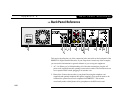
3. Cntrl Out (Serial): For future use.
4. Cntrl Out (IR): For future use.
5. USB (Universal Serial Bus) (2): For future use.
6. Composite Video Outputs (2): If your TV or VCR has a Composite Video jack you
can connect the recorder to your TV or VCR’s Video In using the yellow video
connector on the Composite Video cable (supplied). If you have both a TV and a VCR,
you might use one cable for the TV and another cable (not supplied) for the VCR.
7. L/R Audio Outputs (2 each): If your TV or stereo features Composite Input jacks,
connect the Left (white) and Right (red) Audio Output jacks from the recorder to your
TV or stereo using the L/R Audio cables (supplied). If you have both a TV and a VCR,
you might use one set of L/R Audio cables for the TV and another set (not supplied)
for the VCR; see chapter 1 of this guide for examples. If you are using an S-Video
cable to connect to your TV or VCR, you must use it with the L/R Audio outputs.
Ignore the L/R Audio jacks if you’re using RF Out or Digital Audio Out.
8. S-Video Output: If your TV or VCR features an S-Video input jack, you can connect it
to the recorder using an S-Video cable. S-Video provides a higher quality picture than
composite. If you use the S-Video Output, you must also connect the supplied L/R
Audio outputs (red and white cable ends). When connecting S-Video and the red and
white L/R Audio outputs, do not plug in the yellow Composite Video cable.
9. Digital Audio Out: You can use the Digital Audio Out to connect your recorder to an
A/V receiver with a digital audio input. To do so, you will need an optical audio cable
(not supplied). Ordinarily, your recorder produces tones to indicate when certain