


2
2
.
.
3
3
B
B
a
a
s
s
i
i
c
c
W
W
i
i
r
r
i
i
n
n
g
g
I
I
n
n
s
s
t
t
r
r
u
u
c
c
t
t
i
i
o
o
n
n
s
s
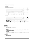
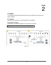
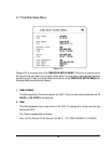
1. Power
Connect the power source or adapter into the power socket.
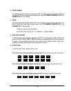
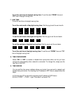
2. Cameras
Connect each cameras video output to the video input on the digital video recorder
shown in diagram 2.1.
Note: At least one camera (CH 1) must be connected before the system is running for
the auto detection of video standard to take effect.
3. Audio Input
The camera audio output or Microphone is connected to the audio input terminal at the
rear panel.
4. Audio Output
Connect the speaker or other audio listening devices to the audio output terminal on the
back of the digital video recorder.
5. Ethernet
The digital video recorder may be viewed from a PC via the LAN connector using a RJ45
Ethernet cable.
6. RS232
9-pin Sub-D control input/output for service purpose.
7. RS485
The digital video recorder can be controlled from a keyboard or a speed dome via
RS485.
Note: This can be done using a serial cable.
8. Main Monitor
Connect the main monitor output connector to a main monitor. The main monitor
displays selected live or recorded cameras in any available format.
Note: The main monitor must be connected in order to make configuration changes,
enter the main menu, or do a playback at the machine.
15