


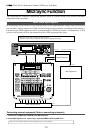

D824/D1624 Reference Manual (MIDI Sync Function)
79
MIDI IN
MIDI OUT
MIDI IN
MIDI THRU
WORD IN
WORD OUT
WORD IN
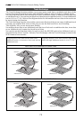
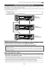
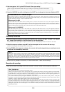
Multitrack system by the slave mode
An example of how to make a multitrack system by interconnecting three recorders in a slave
mode function, will be explained in the following.
A 24 multitrack system can be designed if a D824 is used for this system; if D1624 is used, a 48
multitrack system can be made.
* Initialize the recorder.
* Confirm the program.
* Set all three recorder’s to the same sampling frequency.
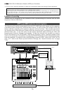
Equipment interconnections
1.From the recorder (#1) to the recorder (#2), connect WORD OUT to WORD IN and MIDI OUT to MIDI IN.
2.From the recorder (#1) to the recorder (#3), connect WORD OUT to WORD IN.
3.From the recorder (#2) to the recorder (#3), connect MIDI THRU (Note!!!) to MIDI IN.
<Notes>
* In order to slave drive the recorder with each other, the best setting is to supply word clock signals together with
MTC from the master.
* As shown in the above schematic, at input or the Word Clock from the master to the second slave, WORD OUT
from the master must always be branched to the second slave. Do not connect the first slave WORD OUT to the
second slave WORD IN .
Setup of the recorder (#1): <Master>
1. Because MTC, which is the reference for sync, is output from the recorder (#1), set the “MIDI sync signal
output setting” of the SETUP mode to “MTC.”
Refer to page “
109
”, SETUP mode “MIDI sync signal output setting” for operating procedure and details.
2. A random frame rate to be used is set by the SETUP mode “MTC Frame rate setting.”
Refer to page “
109
”, SETUP mode “MTC Frame rate setting” for operating procedure and details.
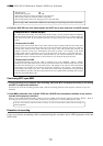
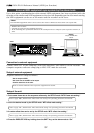
Master <#1>
[Clock Sel?]=Int.
Slave <#2>
[Clock Sel?]=Word
Slave <#3>
[Clock Sel?]=Word