


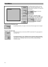
Const Menu
72
Const Menu
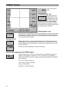
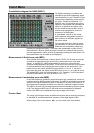
The function constellation diagram can be called up in the operation types, SAT
(DVB-S), TV (DVB-C and DVB-T), TV-IF or return path (DVB-C). Operating the
constellation functions is principally the same in the various operating types. The
differences are described below.
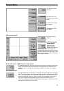
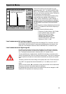
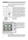
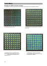
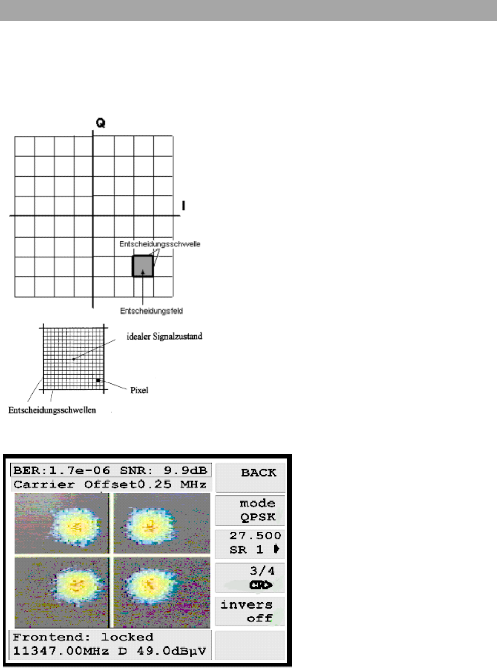
Colour representation of I/Q value pairs
The colour representation of the I/Q value pairs should
simplify the analysis of the constellation diagram in regards to
the occurring error. The colour of the I/Q value pairs changes
with the number of hits on one point within the decision field.
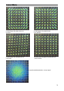
In an ideal case, the I/Q value pairs are always in the middle
of the decision field. However the I/Q value pairs are
influenced by interference on the transmission paths or in the
modulator on the transmitting side. As long as the I/Q value
pairs lie within the decision waves, a clear relation of valence
in the receiver can occur. The decision field is subdivided into
signal subsurfaces, also called pixels. For a black/white
representation, one could not represent the frequency of the
hits of a I/Q value pair on the surface of a pixel. The colour
representation of the MSK 33 allows the frequency of the hits
of a I/Q value pair on the surface of a pixel to be described by
the changing of colour. If many I/Q value pairs meet on a
pixel, RED is represented, however if very few I/Q value pairs
meet on a pixel, blue is represented. Four colours are avail-
able for the assessment of the „scores.“
RED – very many hits
YELLOW – many hits
GREEN – few hits
BLUE – very few hits
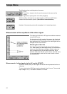
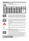
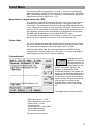
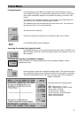
Constellation diagram for QPSK (DVB-S)
For the digital transmission via satellite,
the modulation type QPSK (Quadrature
Phase Shift Keying) is used. Every 2 in-
formation bits are put together to one
symbol and modulate one carrier in its
phase. With this, four conditions are pos-
sible, which a receiver must recognise.
A crosshair with four clouds, which repre-
sent the possible symbols or their fre-
quency in the quadrants appear on the
colour screen.
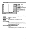
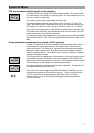
Measurement of the bit error rate (BER)
Since it deals with transmission of binary data for DVB-S, the bit error rate can be
considered as measurement for the occurred transmission error in the data stream.
In the MSK 33, a BER measurement is carried out before the viterbi decoder and
displayed on the screen. The bit error rate is the ratio of the number of received de-
fected bits divided by the entire number of the received bits. The lowest bit error