


Const Menu
76
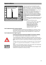
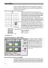
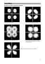
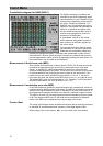
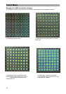
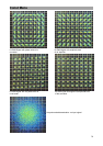
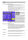
Constellation diagram for QAM (DVB-C)
For digital transmission via cables, the
modulation type QAM (Quadrature Ampli-
tude Modulation) is used. The MSK 33 can
represent the constellation of the modula-
tion types, QAM64 and QAM128. For
QAM 64, every 6 information bits are put
together to one symbol and modulate one
carrier in its amplitude and phase. With
this, 64 conditions are possible, which a
receiver must recognise for correct as-
sessment of a QAM signal.
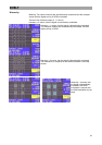
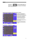
A „chessboard“ with 64 or 128 clouds,
which represent the possible symbols or
their frequency in the fields, appears on
the colour screen.
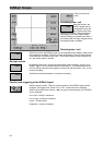
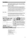
You can select the menu items by press-
ing the buttons on the right of the screen.
Submenus are immediately called up by
pressing the appropriate softkey. The buttons are represented in yellow for acti-
vated functions. Buttons, which have multi-functions, are indicated with an arrow
and are represented in yellow as well. By repeatedly pressing the same button, dif-
ferent parameters can be called up and displayed.
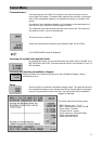
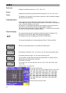
Measurement of the bit error rate (BER)
Since it deals with transmission of binary data for DVB-C, the bit error rate can be
considered as measurement for the occurring transmission error in the data
stream. In the MSK 33, a BER measurement is carried out before the error
correction and displayed on the screen. The bit error rate is the ratio of the number
of received defective bits divided by the entire number of the received bits. The
lowest bit error rate, which the MSK 33 can measure, is 1.0 e-8. If the rate is
lower than this value, the display of the BER jumps to zero „0“ (no longer bit error).
The highest BER, which can be displayed, is 1 e-2. Generally, it can be assumed,
that picture disturbance can occur by a BER of ca. 1 e-3.
Measurement of modulation error rate (MER)
In the DVB measuring guidelines, the measurement size is determined, which are
combined with the broad interfering influences. The MER is calculated to record the
entirety of the signal interference, which is available on the input of this receiver. It
gives instructions regarding the ability of the receiver, to decode a signal correctly.
The MER is the ratio of the average signal performance divided by the error power
in dB. The higher the MER value is, the better the received signal is. Measure-
ments of the MER can be displayed on the upper edge of the screen.
Carrier offset
The carrier offset display shows the difference between the set receiving frequency
on the MSK 33 and the transmission frequency of the digital signal in MHz.
With the help of the cursor buttons, ◄►, you can switch to the next channel.