


Broadband Cable Analysis Measuring System MSK 33 /
MVG
86
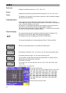
A few functions such as „Clear display,“ „Printout the spectrum“ (prt
123) and switch-over functions can be remotely controlled via the
MVG 10. Refer to the operating manual MVG 10!
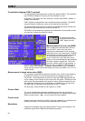
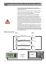
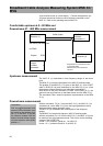
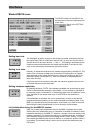
Comfortable upstream 4.0…80 MHz and
Downstream 47…860 MHz measurement
Cable system
with return path amplifiers
ext FBAS
Graphic RGB
Upstream measurement
The MVG 10 (1) wobbulates in free frequency ranges in the return
path.
The MSK 33 (1) receives the signals in the MVG 10 tracking mode.
The graphic of the MSK 33 (1) is given to the MVG 10 via a SCART
cable in RGB (60 Hz) and transmitted to the MSK 33 (2) on a free
downstream channel (attention two-sided band modulation!).
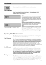
With the aid of the print command „Prt 999“ on the MVG 10 (1), the
spectrum can be printed out on the head station from the MSK 33 (1).
The command „Clear“ clears the spectrum representation on the MSK
33 (1).
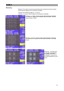
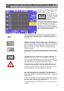
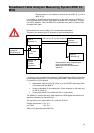
Downstream measurement
With the command „Fkt A 1“ from the MVG 10 (1), the MVG 10 (2) s
switched over via the MSK 33 (1) from the signal generator mode to
the downstream sweep generator mode.
The MVG 10 (2) wobbulates the forward path in free frequency
ranges.
The MSK33 (2) receives the signals in MVG 10 tracking mode.
With the command „Fkt A 0“ from the MVG 10 (1), the MVG 10 (2) can
be reset into the signal generator mode. This occurs via the switching
voltage of the SCART line.
Uscart = 12 V produces Recall no. 1 on MVG 10.
Uscart = 0 V produces Recall Nr. 0 on MVG 10
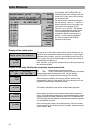
MVG10 (2)
Signal
wobbel-
generator
MVG10
Wobbel-
generator (1)
MSK33
Receiver (1)
MSK33
Receiver (2)
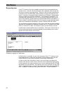
Preparation
First, the signal generator with
external RGB modulation mus
t
be stored on the memory posi-
tion „0“ of the MVG 10 (2) and
the channel sweeper with the
desired channel sweep ranges
must be stored on the memor
y
position „1.“
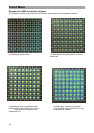
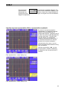
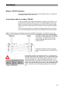
Representation of upstream spectrum
on the head station
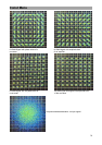
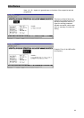
Measurement of the downstream
spectrum