11
206-4227
Rack Installation
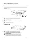
PWR
POWER
12V
Service Port
Feature Port Control Port
RF-OUT
ASI-OUT
RF-OUT
0 dBmV
FIRMWARE VER:
Rx.x
MAC ADDRESS:
<Eth0>
xx:xx:xx:xx:xx:xx
<Eth1>
xx:xx:xx:xx:xx:xx
MODEL: PCS200R DATE: xx/xx/xx
I IIIII IIIIIIII IIIIIIIIIIIIIIIIIIII IIIIIIIIIIIIIIIIIIIIII
*201-1252008*
SSD (OPTIONAL)
MAXIMUM CURRENT +5V DC @ 2.0A
SERVICE USE ONLY
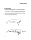
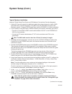
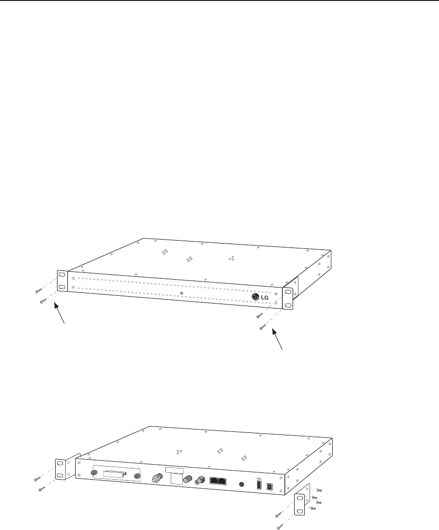
Typical Rack Installation
1. To avoid causing electrostatic (ESD) damage to the PCS200R during installation, attach an
antistatic wrist strap to a properly grounded rack/object and put it on.
2. (Optional) As shipped, the PCS200R mounting brackets are attached ush with the front of
the unit (see diagram a). If desired, the mounting brackets may be detached from the unit
and reattached, for example, so that they are ush with the rear of the unit (see diagram b).
If you wish to change the location/orientation of the mounting brackets, carefully remove
each of the four (M4 x 10 mm) screws and attendant washers (one at and one lock washer
per screw) holding each bracket in place. Then, use the same screws and washers to
reattach the mounting brackets in the desired location.
3. Carefully slide the chassis into a standard 19-inch equipment rack.
4. Use all four mounting screws to secure the chassis to the rack.
PWR
POWER
12V
Service Port
Feature Port Control Port
RF-OUT
ASI-OUT
RF-OUT
0 dBmV
FIRMWARE VER:
Rx.x
MAC ADDRESS:
<Eth0>
xx:xx:xx:xx:xx:xx
<Eth1>
xx:xx:xx:xx:xx:xx
MODEL: PCS200R DATE: xx/xx/xx
I IIIII IIIIIIII IIIIIIIIIIIIIIIIIIII IIIIIIIIIIIIIIIIIIIIII
*201-1252008*
SSD (OPTIONAL)
MAXIMUM CURRENT +5V DC @ 2.0A
SERVICE USE ONLY
To rack
Use at washer and
lock washer with each
M4 x 10 mm mounting
bracket screw.
To rack
(a)
(b)


