


8
206-4227
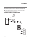
Check the following items before you begin the PCS200R installation and setup procedures.
Note: Once the PCS200R hardware is installed and the initial setup completed, output parameters
are congured in the Pro:Centric server Admin Client. Along with this document, it is recommended
that you have a copy of the Pro:Centric Server Admin Client User Guide readily available.
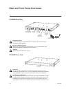
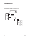
PCS200R
__ Unpack the PCS200R Pro:Centric server unit and all accessories.
PCS200R Accessories: • AC Power Cord and Adapter
• Four M3 x 5 mm screws for (optional) SATA SSD assembly
• Four lock washers for (optional) SATA SSD assembly
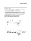
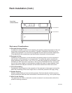
__ Select the location for mounting the PCS200R. Ensure adequate ventilation is available
.
__ Obtain the necessary attachment hardware to mount the PCS200R chassis in its targeted
location.
__ Plan and install the necessary cabling and network (Ethernet) and AC power access for
the PCS200R. You also will need the following to connect a PC directly to the PCS200R for
system setup purposes: FTDI TTL-USB cable (P/N TTL-232R-5V-AJ).
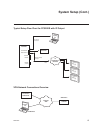
SATA Solid State Drive (Optional)
__ To provide additional media/video playout channels, a customer-supplied SATA solid state
drive may be installed in the SSD slot on the PCS200R rear panel. The solid state drive used
must be UL listed, FCC compliant, and/or other applicable agency-recognized/listed. (Maximum
current draw = +5V DC @ 2.0 Amps)
Video Channel Assignments for RF Output (QAM-B) with Solid State Drive
Each input program is limited to one-half or one-third of the output channel bitrates (Mbps), which
in turn are dependent on the modulation format. 256-QAM modulation supports up to 38.8 Mbps,
and 64-QAM modulation supports up to 26.97 Mbps.
__ Create a channel assignment plan for the installation site, or modify an existing plan to
incorporate the RF output of the PCS200R. Ensure that up to eight contiguous CATV broad-
cast channels are allocated for the PCS200R RF output. The PCS200R uses a 256-QAM or
64-QAM modulation format, thereby occupying approximately 48 MHz of frequency spectrum.
The RF start channel is user-assigned during system setup (in the Admin Client), and the
remaining channels (up to seven) are then automatically assigned per EIA-542 STD CATV
frequency allocation standards. For example, if the RF start channel assignment is channel 2,
the seven remaining channels will be 3, 4, 5, 6, 95, 96, and 97. Refer to EIA-542 STD CATV
frequency allocation tables for further information as required.
The highest available RF channel number for the PCS200R is 135. Thus, to allocate all eight
channels available for PCS200R RF output, the RF start channel must be set no higher than 128.
__ Find a location on the frequency spectrum that is free of existing noise.
Setup Information