


Digital Video Recorder
5
ARI (Alarm Reset In): An external signal to the Alarm Reset In can be used to reset both the Alarm Out
signal and the DVR’s internal buzzer. Mechanical or electrical switches can be wired to the ARI (Alarm
Reset In) and GND (Ground) connectors. The threshold voltage is below 0.3V and should be stable at least
0.5 seconds to be detected. Connect the wires to the ARI (Alarm Reset In) and GND (Ground) connectors.
RS485 Port
Network Port
CAUTION: The network connector is not designed to be connected directly with cable or
wire intended for outdoor use.
Video Out
NOTE: It is possible that the DVR will not detect a VGA monitor automatically if the connected VGA
monitor does not support the auto detection function. In this case, press and hold the
Panic button
on the front panel for 5 seconds or longer to switch the video output to VGA out. Pressing and
holding the Panic button for 5 seconds or longer again returns to the previous video output mode.
Audio In/Out
NOTE: It is the user’s responsibility to determine if local laws and regulations permit recording audio.
NOTE: The DVR does not have amplified audio output, so you will need a speaker with an amplifier.
The DVR does not have a pre-amplifier for audio input, so the audio input should be from an amplified
source, not directly from a microphone.
The DVR can be controlled remotely by an external device or control system, such as a control
keyboard, using RS485 half-duplex serial communications signals. The RS485 connector can
also be used to control PTZ (pan, tilt, zoom) cameras. Connect RX-/ TX- and RX+/TX+ of the
control system to the TX-/RX- and TX+/RX+ (respectively) of the DVR. Refer to Chapter 3 ─
Configuration and the PTZ camera or remote controller manufacture’s manual for configuring
the RS485 connection.
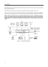
The DVR can be networked using the 10/100Mbps Ethernet connector. Connect a Cat5
cable with an RJ-45 jack to the DVR connector. The DVR can be networked with a
computer for remote monitoring, searching, configuration and software upgrades. Refer to
Chapter 3 ─ Configuration for configuring the Ethernet connections.
A VGA connector is provided so that you can use a standard, multi-sync computer monitor
as your main monitor. Use the cable supplied with your monitor to connect it to the DVR.
Connect the main monitor to the Video Out connector. Connect the Spot monitor to the
SPOT connector as needed.
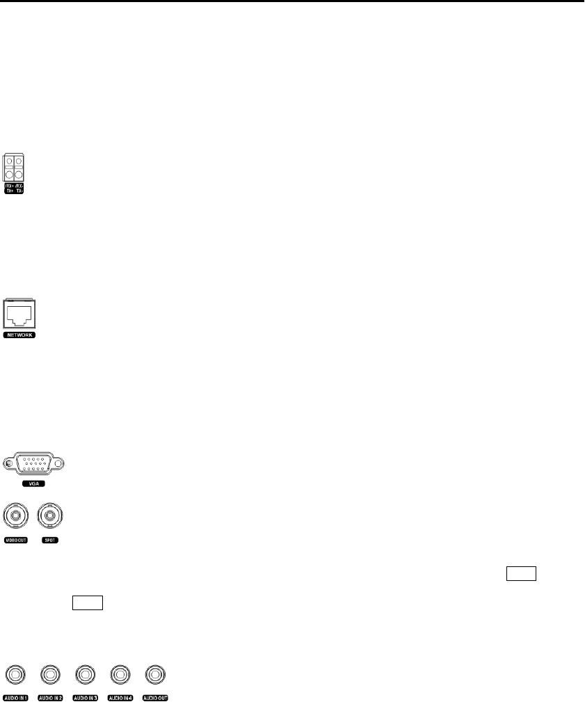
Your DVR can record audio from up to four sources. Connect the audio
sources to Audio In 1, Audio In 2, Audio In 3 and Audio In 4 as needed
using RCA jacks. Connect Audio Out to your amplifier.