


Chapter 2. Connecting 23
Additional connection cables are
not provided with the TV. They are
available at most electronics stores.
IMPORTANT
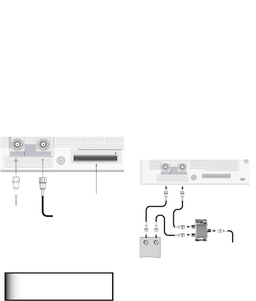
Connecting a Wall Outlet Cable or Cable Box
Wall Outlet Cable
(can be used with a CableCARD™)
Figure 1
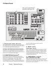
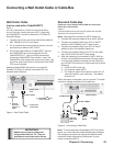
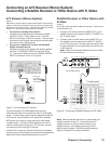
It is very important to connect the incoming cable
for your primary viewing source to ANT-1, especially
for CableCARD™ use and to download TV Guide On
Screen® listings.
1. Connect the primary incoming coaxial lead cable to
ANT 1/MAIN on the TV back panel.
2. For an optional secondary antenna source, connect
an antenna (or cable) to ANT 2/AUX.
3. If you have subscribed to a CableCARD™ service,
the CableCARD can now be inserted into the
CableCARD SLOT. Using a Phillips screwdriver,
remove the CableCARD cover screws. Insert the
CableCARD, then replace the cover and screws. The
top of the card should face in the direction the CARD
TOP arrow indicates.
Additional CableCARD information is on page 84.
Detailed TV Guide On Screen information is in the
separate User’s Manual.
$0.10/&/5
:1C1SJQQJ
*/165
47*%&0
7*%&0
"6%*0
-&'5
.0/0
"6%*0
3*()5
%57$"#-&
7)'6)'
%*(*5"-
"6%*0
065165
$BCMF$"3%64&8*5)"/5$"3%501
2
:
1C
1S
"6%*0
-&'5
.0/0
"6%*0
3*()5
065165
"6%*0
065165
3&$03%
065165
%7*
"OBMPH"VEJP
7*%&0
AUDIO-
LEFT/
(MONO)
"6%*0
3*()5
.0/*503-*/,)%.*
7*%&0JQQJ
"6%*01$.-*/&"3
*&&&
*/165
065165
/FU$PNNBOE
*3&.*55&3
¸
(-JOL
¸
*/165
1$'03)%.*
0/-:)[
7("87("
47("847("
9("9
64&8*5)
$BCMF$"3%
"/5."*/
"/5"69
.0/*503-*/,
$0/530-34$
%57$"#-&
7)'6)'
%*(*5"-
"6%*0
065165
5P"/5."*/
5P"/5"69
57CBDLQBOFM
EFUBJM
$BCMF$"3%
5.
4-05
DPWFSSFNPWFE
1SJNBSZ8BMM
0VUMFU$BCMF
0QUJPOBM
4FDPOEBSZ
"OUFOOBPS
$BCMF
Figure 1. Wall Outlet Cable
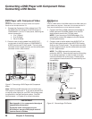
Standard Cable Box
(cable box, other than an HDTV cable box; this setup
allows two-channel PIP)
Figure 2
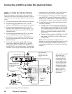
3 coaxial cables and one two-way RF splitter are required.
These are not included with the TV.
Note: See page 29 to connect an HDTV cable box.
1. Connect the incoming cable to IN on an RF splitter.
2. Connect one coaxial cable from OUT on the RF
splitter to ANT-1 MAIN on the TV back panel.
3. Connect one coaxial cable from OUT on the RF
splitter to IN on the standard cable box.
4. Connect one coaxial cable from OUT on the cable
box to ANT-2 AUX on the TV back panel.
5. After the cable box is connected to ANT-2 AUX as
shown, use the NetCommand menu Change option
to change the default connection for the cable box,
go to the RF Connection for Cable screen and do the
following:
a. Check the RF check box.
b. For antenna, select ANT-2.
c. For Channel, select the channel to which the TV
must be tuned for your cable box. The default
channel is 3.
When this setup is complete, you can use the TV remote
control to change channels on the cable box.
$0.10/&/5
:1C1SJQQJ
*/165
47*%&0
7*%&0
"6%*0
-&'5
.0/0
"6%*0
3*()5
%57$"#-&
7)'6)'
%*(*5"-
"6%*0
065165
$BCMF$"3%
64&8*5)
"/5$"3%501
2
:
1C
1S
"6%*0
-&'5
.0/0
"6%*0
3*()5
065165
"6%*0
065165
3&$03%
065165
%7*
"OBMPH"VEJP
7*%&0
AUDIO-
LEFT/
(MONO)
"6%*0
3*()5
.0/*503-*/,)%.*
7*%&0JQQJ
"6%*01$.-*/&"3
*&&&
*/165
065165
/FU$PNNBOE
*3&.*55&3
¸
(-JOL
¸
*/165
1$'03)%.*
0/-:)[
7("87("
47("847("
9("9
64&8*5)
$BCMF$"3%
"/5."*/
"/5"69
.0/*503-*/,
$0/530-34$
%57$"#-&
7)'6)'
%*(*5"-
"6%*0
065165
$BCMF$"3%
64&8*5)
"/5$"3%501
*/
065
*/
065
065
5808":41-*55&3
57CBDLQBOFM
$BCMFCPY
CBDLQBOFM
EFUBJM
3'
4QMJUUFS
5P"/5."*/
5P"/5"69
*ODPNJOH
$BCMF
Figure 2. Connecting a Cable Box
Note: To use a cable box connected to ANT-2 as shown
above, you must make the noted NetCommand changes.
The changes are required to change the NetCommand
cable-box default connection (Component-1) to the
actual connection (ANT-2).