


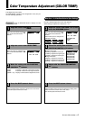
PLASMA MONITOR
ⅥⅥⅥ
† 51
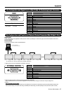
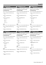
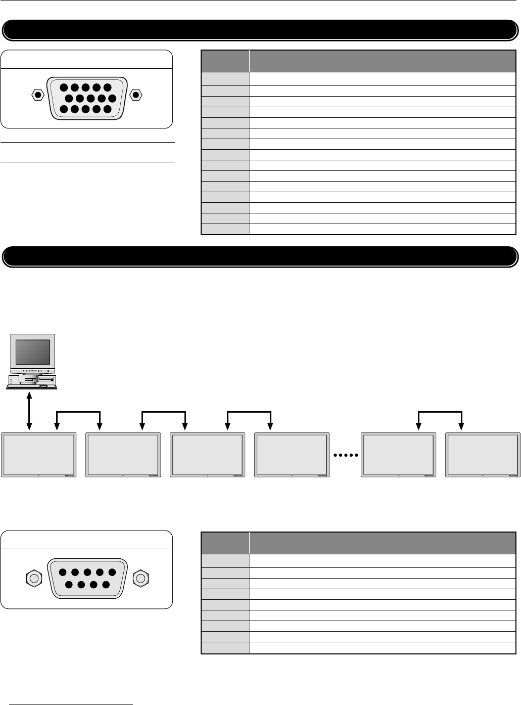
Pin No. Signal (Analog)
1Red
2 Green or sync-on-green
3 Blue
4 Ground
5 Ground
6 Red ground
7 Green ground
8 Blue ground
9 No connection
10 Sync signal ground
11 Ground
12 Bi-directional DATA (SDA)
13 Horizontal or composite sync
14 Vertical sync
15 Data clock
Pin Configuration and Signal Level of Mini D-Sub 15-Pin (Analog) Input Connector
Appendix
RGB1
1
2
3
4
5
6
7
8
9
10
11
121314
15
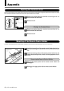
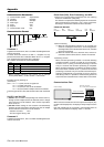
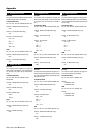
Pin No. Function
1 No connection
2 RXD (Receive data)
3 TXD (Transmit data)
4 No connection
5 Ground
6 No connection
7 RTS (Ready to send) * Connected internally to pin 8.
8 CTS (Clear to send) * Connected to pin 7 inside the main unit.
9 No connection
EXTERNAL CONTROL
45321
6789
Signal level
VIDEO signal : 0.7Vp-p (Analog)
Sync signal : TTL level
Pin Configuration and Functions of External Control Connector (Mini D-Sub 9 -Pin)
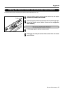
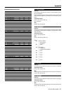
Application
These specifications are applicable to NEC plasma monitors (including 42- and 50-inch types) and communications control from
external equipment.
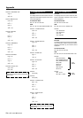
Connections
Connections should be made as described below.
1)Display-side connector: EXTERNAL CONTROL connector
2)External equipment side connector: Serial port (RS-232C) connector
See the specifications of the connected equipment for information about the type of connector and pin assignment.
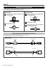
3)Wiring
Use a crossed (reverse) cable.
Wire the cable so that each pair of data lines cross between the two devices. These data line pairs are RXD (Receive data) and
TXD (Transmit data), DTR (DTE side ready) and DSR (DCE side ready), and RTS (Ready to send) and CTS (Clear to send).
*A maximum of 4 units can used with a cascade connection.
External equipment
e.g., Personal computer
PDP1 Display
PDP4 Display
PDP3 DisplayPDP2 Display PDP8 Display PDP9 Display