


30
Connecting—Continued
This section shows how to connect the DV-SP1000/
DV-SP1000E to a standard TV, in which the TV handles
both the video and audio. If your TV has a Dolby Pro
Logic decoder built-in, you’ll be able to enjoy DVDs that
bear the Dolby Surround logo.
To fully enjoy the Dolby Digital and DTS soundtracks
available on most DVD-Video discs, or the multichannel
audio of DVD-Audio and SACD, you need a suitable AV
receiver (see page 36).
The DV-SP1000/DV-SP1000E has three types of video
output for use with standard TVs: component video,
S-Video, and composite video.
Component video offers the best picture quality, so if
your TV supports it, use a commercially available com-
ponent video cable to connect the DV-SP1000/
DV-SP1000E’s COMPONENT VIDEO OUT to the
component video input on your TV. If your TV supports
progressive scanning, you must use a component video
connection to take advantage of it.
If you don’t have component video, S-Video offers bet-
ter picture quality than composite video, so if your TV
supports it, use the supplied S-Video cable to connect the
DV-SP1000/DV-SP1000E’s S VIDEO VIDEO OUT to
an S-Video input on your TV. Failing that, use the sup-
plied composite video cable to connect the DV-SP1000/
DV-SP1000E’s VIDEO VIDEO OUT to a composite
video input on your TV.
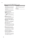
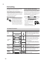
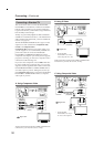
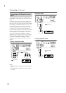
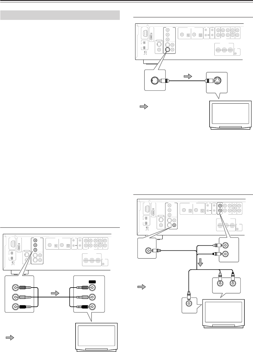
A. Using Component Video
Audio connection not shown here. Make a suitable audio
connection to your TV, AV receiver, or amp.
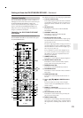
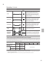
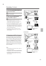
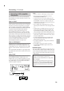
B. Using S-Video
Audio connection not shown here. Make a suitable audio
connection to your TV, AV receiver, or amp.
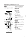
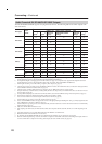
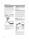
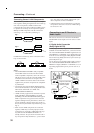
C. Using Composite Video
Connecting a Standard TV
OUT
D. MIX FRONT SURR
1
CENTER SURR
2
L
R
L
R
SUB
WOOFER
IN
REMOTE
CONTROL
VIDEO OUT
COMPONENT
S VIDEO VIDEO
Y
P
B
PR
1
+
21
RS
232
IR
SURR MODE
(
AUDIO OUT
)
IN
12
V
TRIGGER
YPB PR
COAXIAL OPTICAL OPTICALCOAXIAL
DIGITAL
1
DIGITAL
2
VIDEO
S VIDEO
HDMI
VIDEO IN
AUDIO OUT
HD VIDEO OUT
COMPONENT
AUDIO OUT
S400
(
AUDIO
)
OUT
VIDEO OUT
COMPONENT
Y
IN
P
B
PR
Y
P
B
PR
TV
Signal flow
Component
video cable
(RCA)
OUT
D. MIX FRONT SURR
1
CENTER SURR
2
L
R
L
R
SUB
WOOFER
IN
REMOTE
CONTROL
VIDEO OUT
COMPONENT
S VIDEO VIDEO
Y
P
B
PR
1
+
21
RS
232
IR
SURR MODE
(
AUDIO OUT
)
IN
12
V
TRIGGER
YPB PR
COAXIAL OPTICAL OPTICALCOAXIAL
DIGITAL
1
DIGITAL
2
VIDEO
S VIDEO
HDMI
VIDEO
IN
AUDIO OUT
HD VIDEO OUT
COMPONENT
AUDIO OUT
S400
(
AUDIO
)
OUT
S VIDEO
VIDEO OUT
S VIDEO IN
TV
S-Video cable
(supplied)*
Signal flow
* The DV-SP1000/
DV-SP1000E’s two S-Video
sockets output the same video
OUT
D. MIX FRONT SURR
1
CENTER SURR
2
L
R
L
R
SUB
WOOFER
IN
REMOTE
CONTROL
VIDEO OUT
COMPONENT
S VIDEO VIDEO
Y
P
B
PR
1
+
21
RS
232
IR
SURR MODE
(
AUDIO OUT
)
IN
12
V
TRIGGER
YPB PR
COAXIAL OPTICAL OPTICALCOAXIAL
DIGITAL
1
DIGITAL
2
VIDEO
S VIDEO
HDMI
VIDEO IN
AUDIO OUT
HD VIDEO OUT
COMPONENT
AUDIO OUT
S400
(
AUDIO
)
OUT
VIDEO OUT
VIDEO
VIDEO IN
D. MIX
L
R
AUDIO OUT
LR
ANALOG INPUT
TV
AV RCA cable
(supplied)*
* The DV-SP1000/
DV-SP1000E’s two compos-
ite video sockets output the
(yellow)
(yellow)
(white)
(white)
(red)
(red)
Signal flow