


24 – ENGLISH
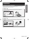
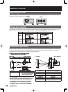
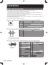
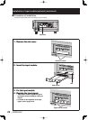
Before starting connection
Before connection, read carefully the instruction manual for the device to be connected.
Turning off the power switch of the devices before connecting cables.
If any connection cable is not supplied with the device, or if no optional cable is available for connection of the
device, prepare a necessary system connection cable to suit the device.
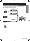
Video signals containing too much jitter may cause the images on the screen to randomly wobble or wafture. In
this case, a time base corrector (TBC) must be connected.
The projector accepts the following signals: video, S-Video, analog RGB, DVI-D and signals which are compatible
with the optional input module (p. 27).
Some PC models cannot be connected to the projector.
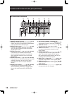
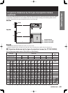
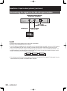
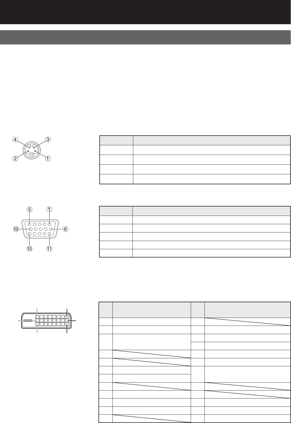
The pin-out and signal names of the S-VIDEO IN terminal are shown in the diagram below.
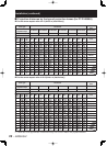
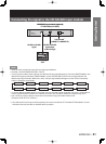
The pin-out and signal names of the RGB2 IN terminal are shown in the diagram below.
&, -, 0, and 3 are not assigned.
( - +, . and / are GND terminals.
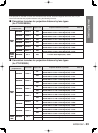
The pin-out and signal names of the DVI-D IN terminal are shown in the diagram below.
•
•
•
•
•
•
●
●
●
Outside view
Pin No. Signal
#
Ground (luminance signal)
$
Ground (color signal)
%
Luminance signal
&
Color signal
Outside view
Pin No. Signal
#
Ground (luminance signal)
$
Ground (color signal)
%
Luminance signal
&
Color signal
Pin No. Signal
#
R/PR
$
G/G • SYNC/Y
%
B/PB
1
HD/SYNC
2
VD
Outside view
Pin No. Signal
#
R/PR
$
G/G • SYNC/Y
%
B/PB
1
HD/SYNC
2
VD
Outside view
#+
=
4
5
-
Outside view
Pin
No.
Signal
Pin
No.
Signal
#
T.M.D.S data 2–
1
$
T.M.D.S data 2+
2
+5V
%
T.M.D.S data 2 / 4 shield
3
Ground
4
Hot plug detection
&5
T.M.D.S data 0-
(6
T.M.D.S data 0+
)
DDC clock
7
T.M.D.S data 0 / 5 shield
*
DDC data
+8
-
T.M.D.S data 1–
9
.
T.M.D.S data 1+
:
T.M.D.S clock shield
/
T.M.D.S data 1 / 3 shield
;
T.M.D.S clock+
0=
T.M.D.S clock–
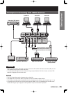
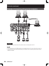
Connection