


22 203987 Rev A RCP2-1000 RM Remote Controller Operations Manual
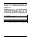
3.2.1.5 Sys Info Page 5
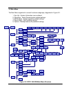
Page 5 shows settings related to the HPA 1:1 Redundant System operation.
• Mode - indicates HPA operational mode. Value can be set to "1:1" for 1:1 redun-
dancy mode and "Stdaln" for stand alone mode;
• Stby. - shows HPA standby state selection. "Hot" for hot standby operation (HPA
retains unmuted state during standby period) and "Cold" for cold standby (HPA al-
ways mutes itself in standby mode and unmutes when switched back on-line).
• Ctrl. - shows HPA control style. "Local" - both local and remote control are sup-
ported and "Remote" when only remote control provided (keypad locked);
• Switch - indicates switching style. "Auto" for automatic fault tracking/switching and
"Manual" if redundancy switching provides by operator himself.
• Unit - redundancy topological factor. "HPA1" for HPA connected to the RF switch
port 1 or 4 (Online Position 1 of the RF switch). "HPA2" for HPA connected to the
RF switch port 2 or 3 (Online Position2 of the RF switch).
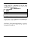
3.2.1.6 Sys Info Page 6
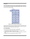
This page shows the status of the HPA’s internal power supplies
• PS1(V) - main power supply 1 output voltage with resolution of 0.1V. Normal output
voltage should be in range of 11 to 13 V.
• PS2(V) - main power supply 2 output voltage.
• Boost1(V) - booster power supply 1 output voltage with resolution of 0.1V. Normal
range 24 to 30 V (typical 28V);
• Boost2(V) - booster power supply 2 output voltage.
• DC (A) - total DC current draw by RF modules from main power supply. Value var-
ies depending on the power level of the HPA. If the HPA is in the mute state current
drops to 0 to 5 A range. It's normal.
3.2.1.7 Sys Info Page 7
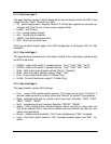
This page shows RF module related faults and conditions.
• Regulator - RF module regulator low voltage fault. Values - "Fault" or "Normal";
• DC Current - low DC current fault. Values -"Fault" or "Normal";
• Temperature - high temperature fault. Values - "Fault" or "Normal";
• Temp.(C) - internal RF module plate temperature in Celsius.
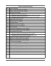
3.2.1.8 Sys Info Page 8
This page shows individual RF module states in multi-module HPA.
If a particular module does not exist in the HPA configuration, the value shows
"N/A" (not available). Each value represents the summary fault state of the individual
RF module, which includes Voltage, Current and Temperature state as well as quality
of data connection with module.