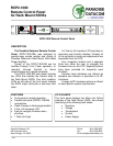
RCP2-1000
Remote Control Panel
for Rack Mount SSPAs
203211 Rev C ECO 3171
3 OF 4
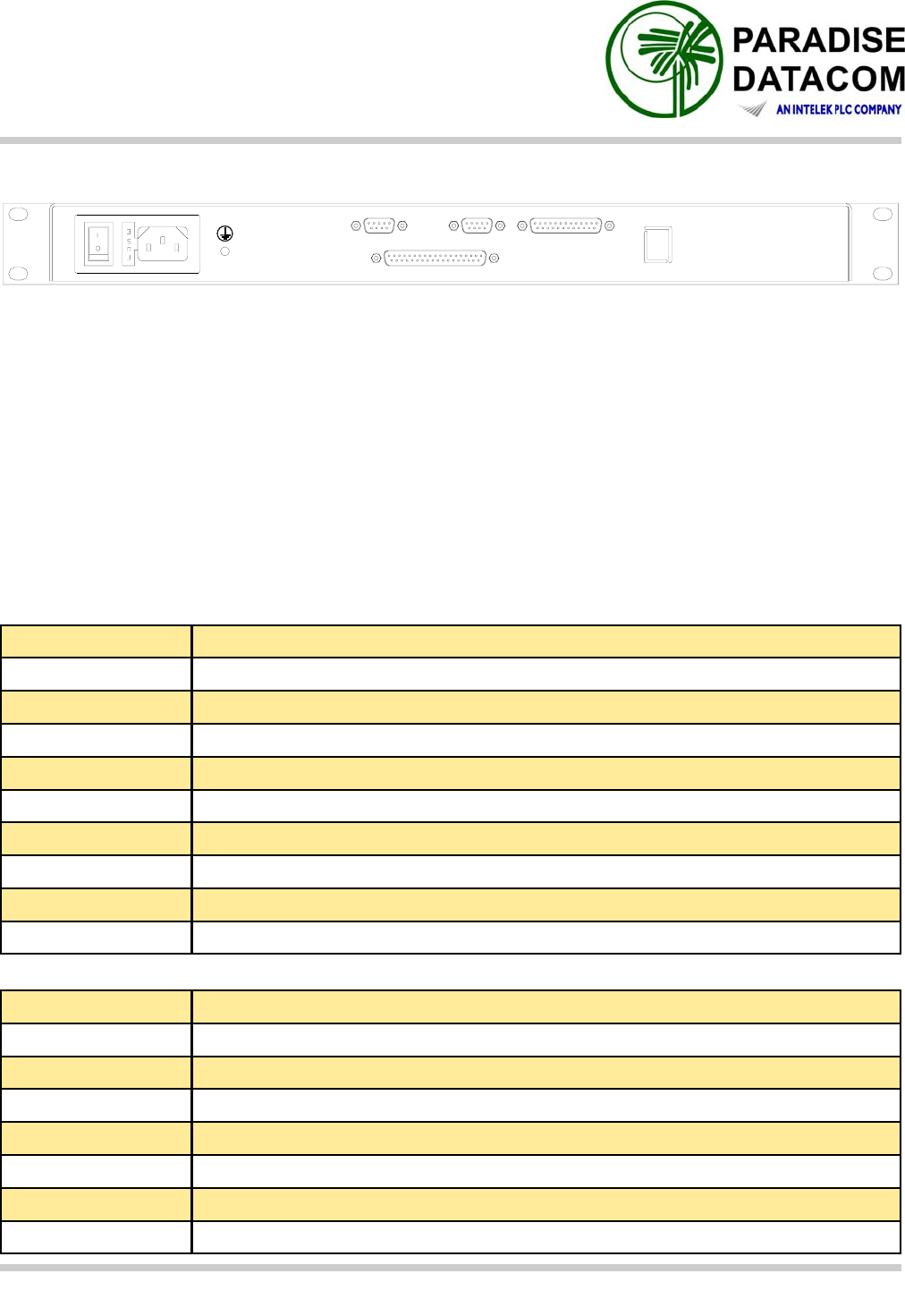
Rear Panel Connectors and Pin Identification
Main Serial Port (J4) Pin Outs
Pin Function
1 RS485 TX+ (HPA Transmit +)
2 RS485 TX- (HPA Transmit -)/RS232 TX
3 RS485 RX+ (HPA Receive -)/RS 232 RX
4 RS485 RX- (HPA Receive +)
5 GND
6 Service Request 1 Form C relay NC contact (Closed on HPA Summary Fault)
7 Service Request Common Form C relay common contact
8 Service Request 2 Form C relay NO contact (Opened on HPA Summary Fault)
9 120 Ohm termination (must be connected to pin 4 in order to enable termination)
J9 ETHERNET
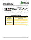
J4 SERIAL MAIN J6 PROGRAMJ5 SERIAL LOCAL
J7 PARALLEL I/O
J1
PS1
The RCP2-1000-RM includes two serial communications ports (J4 and J5). The Main Serial
Port (J4) allows remote communication with a personal computer. The Local Serial Port (J5)
allows a serial interface with a remote Rack Mount SSPA. Interface parameters are set by in-
ternal RCP hardware and cannot be reconfigured by user.
In addition, the RCP2-1000-RM features a 37-pin Parallel I/O port that contains a series of
contact closures for monitoring remote SSPA faults as well as opto-isolated inputs for control-
ling some of the SSPA functions. Inputs react on the closure to ground.
The following tables show the pin outs for the Main Serial Port (J4), Local Serial Port (J5) and
Parallel I/O Port (J7).
Local Serial Port (J5) Pin Outs
Pin Function
1 RS485 RX+
2 RS485 RX-
3 RS485 TX-
4 RS485 TX+
5 GND
6,7,8 Not Used
9 120 Ohm termination (must be connected to pin 1 in order to enable termination)


