30 203987 Rev A RCP2-1000 RM Remote Controller Operations Manual
4.2 Design Philosophy
The RCP2-1000 RM remote controller was designed to achieve a new level in high reli-
ability, maintenance free operation. A tightly integrated modular assembly approach
has been used to realize a versatile controller while maintaining its user friendly opera-
tor interface. Four basic building blocks are combined in the unit:
1. Digital Core Board
2. I/O Board Assembly
3. Liquid Crystal Display
4. Front Panel Membrane Keypad
4.2.1 Digital Core Board
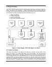
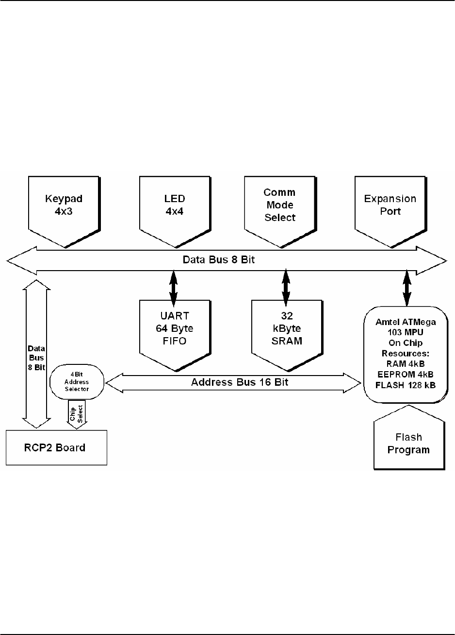
The Digital Core Board is the heart of the redundant controller. At the center of the
digital core board is the Atmel AVR Mega 128 microcontroller. The microcontroller
operates at a clock speed of 7.68 MHz. It provides control functions through the use of
an 8 bit wide data bus and 16 bit addressing bus for most of the peripheral devices. A
separate UART and collision detector is provided for extremely robust serial interfacing
with multi-host networks. All digital I/O lines are protected by opto-coupling or transient
absorbing devices. The power supply lines are protected by current limiting devices.
Figure 4-1: Block Diagram, RCP2-1000 Digital Core Board


