


12 Pelco Manual C650M (12/98)
4.0 INSTALLATION
4.1 PRE-INSTALLATION CAUTIONS
1. Provide secure power to system components. Prevent overloading or shorting
by dedicating power circuits to the surveillance equipment. Restrict access to
the surveillance system circuit breakers, switches, and equipment power cords.
2. Surveillance system components must be operationally compatible. Time-lapse
recording speeds and dwell times of any accessory switching equipment must
be compatible with each other.
3. The TLR2024 time-lapse VCR provides multiple alarm recording speeds so it
is important that alarm triggering of components be operationally compatible.
Refer to Section 2.1 for information on time-lapse recording.
4. Complete all system hookups (camera, multiplexer, etc.) before installing the
VCR in a location where you cannot access its rear panel.
4.1.1 Securing the VCR Controls
Protect surveillance equipment to forestall tampering. We recommend putting the
recorder in a secure VCR cabinet. Pelco offers such units–the RM2000, which is a
rack kit for a single VCR, and the RM2004, which is a rack kit for four VCRs.
4.1.2 Monitor Tips
• Pelco recommends using a CCTV monitor.
• Some monitors may cause picture vibration or picture distortion at the top or
bottom of the image during still or normal playback. (Refer to Section 9.4.3 for
information.)
A television may be unable to provide a stable picture without vibration or distortion.
4.2 INSTALLATION
1. Remove the VCR and all cables from the box.
2. Place the VCR in a suitable location.
• If the location is unsecured, refer to Section 4.1.1 for information about
products to lock up the VCR.
• Do all system hookups (camera, multiplexer, etc.) before installing the
VCR in a location where you cannot access its rear panel.
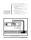
3. If installing in a rack, place the VCR in the rack before making cable and power
connections. Refer to the documentation included with the rack kit for specific
installation instructions.
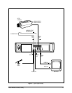
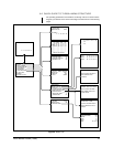
4. If you are not using a switcher, refer to Figure 1.
• Connect the camera (video output) to the rear of the VCR (video input
BNC). Connect the VCR (video output BNC) to the monitor (video input).
• Connect the alarm input to the VCR (SET IN and GND [ground] termi-
nals).
• If you are using a 600 Ω microphone, connect it to the VCR (MIC IN jack).
Connect the VCR (audio output connector) to the monitor (audio input).
5. If you are using a switcher, refer to Section 4.3.