


Pelco Manual C650M (12/98) 23
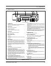
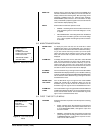
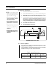
MODE OUT Sets the state in which the signal output at the MODE OUT
terminal is switched to active. When you turn the JOG dial, the
display switches in the following order: REC (recording), PLAY
(playback), POWER (power on), TAPE IN (tape inserted),
TAPE REMAIN (three minutes in 2H mode before the tape
ends), CLOCK ADJ (output the signal for one second when the
clock indicates 00[min]:00[sec]), REC.
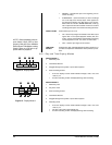
REC IN Sets the REC IN terminal’s operation mode.
• SERIES – Recording starts when the REC IN terminal is
short-circuited to ground or a low-level voltage (0 to +1.6V)
is applied.
• REC-START/STOP – Recording starts when the REC IN
terminal is short-circuited to ground or a low-level voltage
(0 to +1.6V) is applied. Recording stops if this connection
is removed.
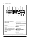
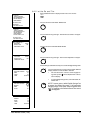
6.8 MAINTENANCE MENU
POWER LOSS To display the power loss list, turn the JOG dial to select
LIST POWER LOSS LIST. Turn the SHUTTLE ring to the right to
display the list. Power failure start times are stored in memory,
so you can confirm when they occurred. Up to three power
failure start times will be displayed. If there were more than
three, the first and last two power failure start times will be
displayed.
ALARM LIST To display the alarm list, turn the JOG dial to select ALARM
LIST. Turn the SHUTTLE ring to the right to display the list.
Alarm record start times are stored in memory, so you can
confirm when they occurred. Up to three alarm record start
times will be displayed. If there were more than three, the first
and last two alarm record start times will be displayed.
ALL MENU Turn the SHUTTLE ring to the right and the words ALL MENU
INITIALIZE INITIALIZE will be displayed. When you turn the SHUTTLE ring
to the left, all settings (except the TIMER RECORDING setting)
will be cleared. Turn the SHUTTLE ring to the right to return to
the Maintenance menu.
POWER LOSS Turn the SHUTTLE ring to the right and the words POWER
LIST CLEAR LOSS LIST CLEAR will be displayed. When you turn the
SHUTTLE ring to the left, the list will be cleared. Turn the
SHUTTLE ring to the right to return to the Maintenance menu.
ALARM LIST Turn the SHUTTLE ring to the right and the words ALARM LIST
CLEAR CLEAR will be displayed. When you turn the SHUTTLE ring to
the left, the list will be cleared. Turn the SHUTTLE ring to the
right to return to the Maintenance menu.
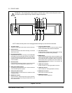
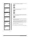
6.9 FIRST TIME SET UP MENU
TAPE END Sets the VCR’s state of operation when the tape runs out during
recording.
• STOP – The tape stops. “End” appears on the fluorescent
display and “Tape End” on the monitor. When CALL OUT
is set to WRNG•TAPE END, a call signal is output from
the CALL terminal.
• REWIND – Rewinds the tape to the beginning and stops
(except during timer recording). When CALL OUT is set
to WRNG•TAPE END, a call signal is output for two sec-
onds from the CALL terminal.
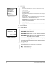
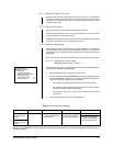
<MAINTENANCE>
POWER LOSS LIST
ALARM LIST
ALL MENU INITIALIZE
POWER LOSS LIST CLEAR
ALARM LIST CLEAR
<REPEAT REC TIMES> 0
<ELAPSED TIME> 0H
Figure 12. Maintenance Menu
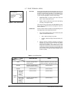
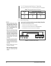
<FIRST TIME SET UP>
TAPE END STOP
QUASI V-SYNC ON
TIME DATE ADJUST
Figure 13. First Time Set Up
Menu