


Connecting up
02
12
En
Chapter 2
Connecting up
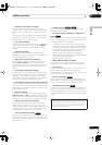
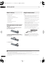
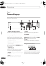
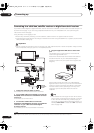
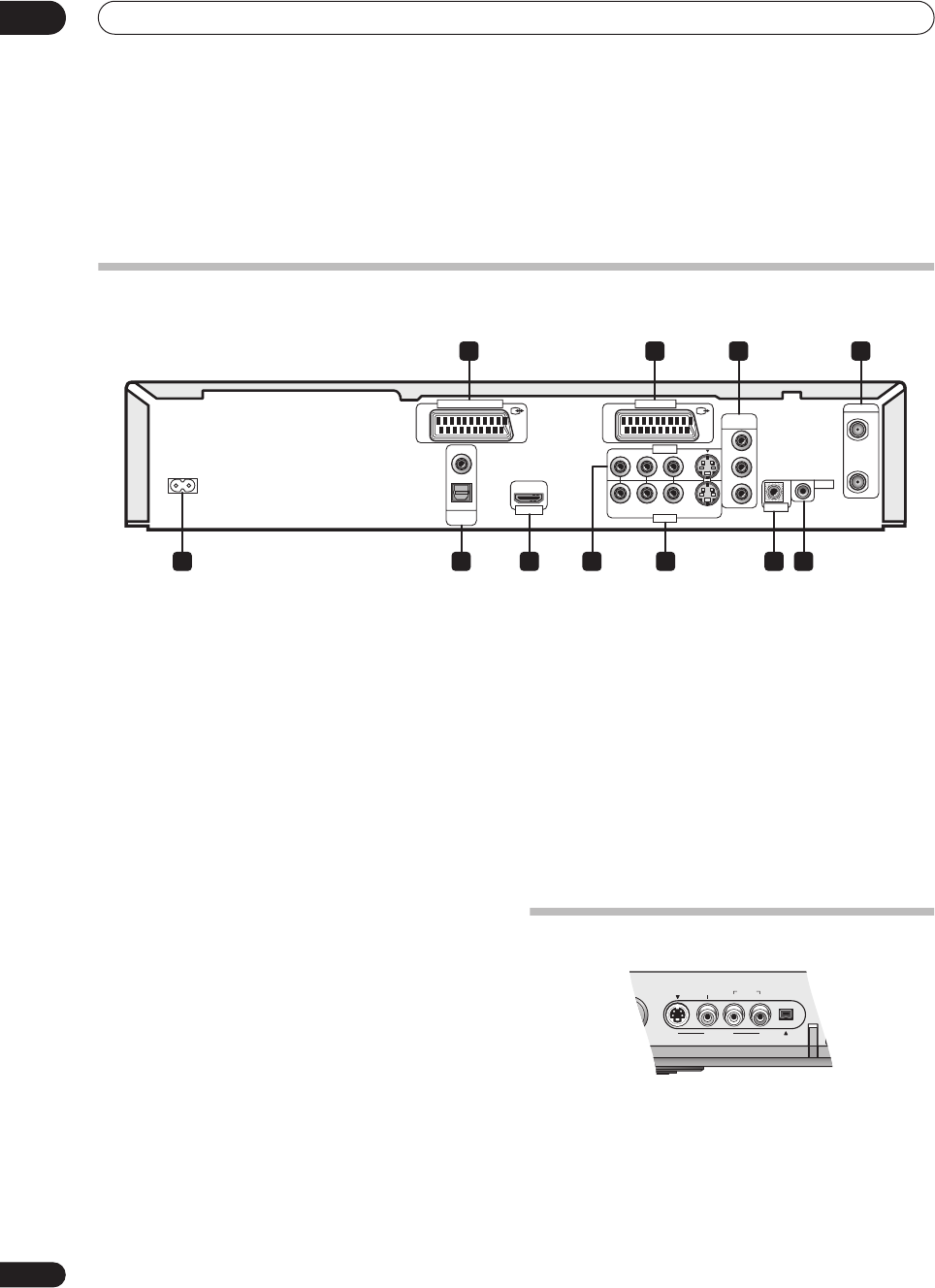
Rear panel connections
1 AV2(INPUT 1/DECODER) AV connector
Audio/video input/output SCART-type AV connector for
connecting to a VCR, or other equipment with a SCART
connector. The input accepts video, S-video and RGB.
See
AV2/L1 In
on page 113 for how to set this up.
2 AV1(RGB)-TV AV connector
Audio/video output SCART-type AV connector for
connecting to a TV or other equipment with a SCART
connector. The video output is switchable between video,
S-video and RGB. See page
AV1 Out
on page 112 for how
to set this up.
3 COMPONENT VIDEO OUT
A high-quality video output for connecting to a TV or
monitor with a component video input.
4 ANTENNA IN/OUT
Connect your TV antenna to the
ANTENNA IN
jack. The
signal is passed through to the
ANTENNA OUT
jack for
connection to your TV.
5 AC IN – Power inlet
6 DIGITAL AUDIO OUT
Coaxial and optical digital audio jacks for connecting to
an AV amplifier/receiver, Dolby Digital/DTS/MPEG
decoder or other equipment with a digital input.
7 HDMI OUT
HDMI output providing a high quality interface for digital
audio and video.
8 INPUT 3
Stereo analog audio, video and S-video inputs for
connection to a VCR or other source component.
9 OUTPUT
Stereo analog audio, video and S-video outputs for
connection to a TV or AV amplifier/receiver.
10 CONTROL IN
Use to control this recorder from the remote sensor of
another Pioneer component with a
CONTROL OUT
terminal and bearing the Pioneer
mark. Connect the
CONTROL OUT
of the other component to the
CONTROL
IN
of this recorder using a mini-plug cord.
11 G-LINK
Use to connect the supplied G-LINK cable to enable
GUIDE Plus+ to control an external satellite receiver, etc.
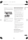
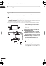
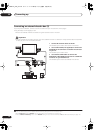
Front panel connections
On the left side of the front panel a flip-down cover hides
a second audio/video input, consisting of an S-video and
standard (composite) video jack, and stereo analog audio
jacks. Here you’ll also fine a DV input/output i.LINK
connector. This is for connection to a DV camcorder.
COMPONENT
VIDEO OUT
AC IN
DIGITAL
AUDIO OUT
OPTICAL
COAXIAL
CONTROL
G-LINK
IN
IN
OUT
ANTENNA
RL
AUDIO
VIDEO
S-VIDEO
Y
P
B
PR
OUT PUT
HDMI OUT
IN PUT 3
AV 1 (RGB) - TVAV 2 (INPUT 1/DECODER)
1 2
965 87 1110
3 4
AUDIO
INPUT 2
DBY
/
ON
L(MONO)
R
S-VIDEO VIDEO
DV
IN
/
OUT
DVR-04_HDD_UK.book 12 ページ 2004年9月10日 金曜日 午後7時3分