


Connecting up
02
16
En
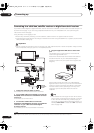
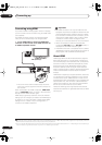
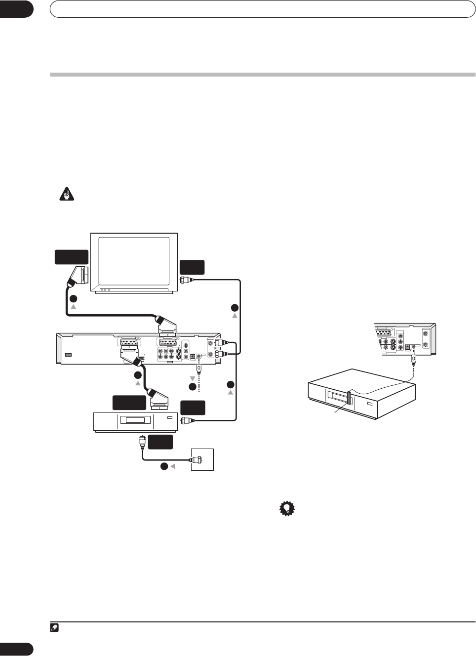
Connecting to a cable box, satellite receiver or digital terrestrial receiver
If you have a cable, satellite or digital terrestrial receiver with a built-in decoder, connect it to this recorder and your TV
as shown on this page.
1
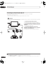
If you are using a separate decoder box for your cable/satellite TV, set up following the
instructions on the next page.
Using the setup on this page you can:
• Record any channel by selecting it on the cable box, satellite receiver or digital terrestrial receiver.
• Change channels and set timer recordings on the external receiver using the GUIDE Plus+ system (via the G-LINK
cable, and after setting up).
Important
• Do not connect this recorder to your TV ‘through’ your VCR, satellite receiver or other component. Always connect
each component directly to your TV or AV amplifier/receiver.
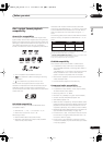
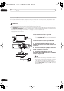
1 Connect RF antenna cables as shown.
This enables you to watch and record TV channels.
2 Use a SCART cable (not supplied) to connect the
AV1(RGB)-TV AV connector to a SCART AV connector
on your TV.
This enables you to watch discs.
3 Use another SCART cable to connect the
AV2(INPUT 1/DECODER) AV connector to a SCART AV
connector on your cable box/satellite/digital
terrestrial receiver.
This enables you to record scrambled TV channels.
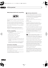
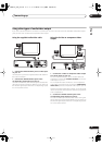
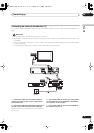
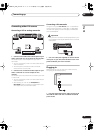
4 Plug the supplied G-LINK cable to the G-LINK
jack.
This enables you to control the tuner in the external
receiver through GUIDE Plus+.
Position the IR transmitter end of the G-LINK cable so
that the IR receiver on your cable/satellite/digital
terrestrial receiver will pick up the control signals (see
diagram).
See the manual that came with your cable/satellite/
digital terrestrial receiver if you’re not sure where the IR
receiver is on the front panel. Alternatively, experiment
with the remote control, operating it from very close
range until you find the place where the receiver
responds.
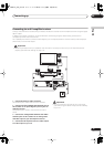
Tip
• This recorder has a ‘through’ function which allows
you to record a TV program from the built-in TV tuner
in this recorder while watching a video playing on
your VCR. (To use this feature when the recorder is in
standby,
Power Save
must be set to
Off
—see
Power
Save
on page 108).
Note
1 The diagram shows SCART video connections, but you can alternatively use any of the other audio/video connections.
TV
Satellite dish/
antenna/cable T
V
wall outlet
Cable/Satellite/
Digital Terrestrial
receiver
COMPONENT
VIDEO OUT
AC IN
DIGITAL
AUDIO OUT
OPTICAL
COAXIAL
CONTROL
G-LINK
IN
IN
OUT
ANTENNA
RL
AUDIO
VIDEO
S-VIDEO
Y
P
B
P
R
OUT PUT
HDMI OUT
IN PUT 3
AV 1 (RGB) - TVAV 2 (INPUT 1/DECODER)
SCART AV
CONNECTOR
SCART AV
CONNECTOR
ANTENNA
IN
ANTENNA
OUT
ANTENNA
IN
1
1
2
3
1
4
COMPONENT
VIDEO OUT
CONTROL
G-LINK
IN
IN
OUT
ANTENNA
RL
AUDIO
VIDEO
S-VIDEO
Y
P
B
P
R
OUT PUT
IN PUT 3
AV 1 (RGB) - TV
G-LINK cable
DVR-04_HDD_UK.book 16 ページ 2004年9月10日 金曜日 午後7時3分