


19
Hookups and Settings
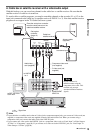
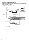
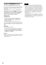
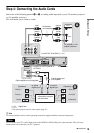
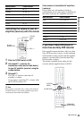
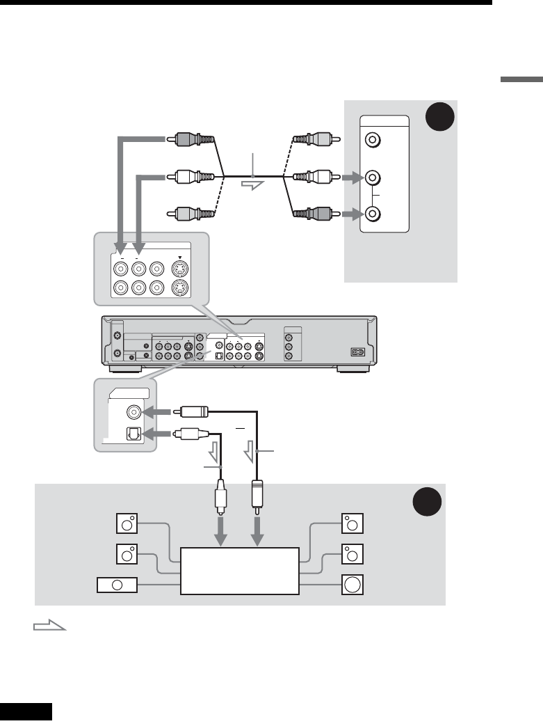
Step 4: Connecting the Audio Cords
Select one of the following patterns A or B, according to the input jack on your TV monitor, projector,
or AV amplifier (receiver).
This will enable you to listen to sound.
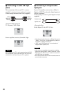
z Hint
For correct speaker location, see the operating instructions supplied with the connected components.
Note
Do not connect your TV’s audio output jacks to the LINE IN (AUDIO L/R) jacks at the same time. This will cause
unwanted noise to come from your TV’s speakers.
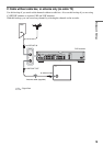
VHF/UHF
IN
COMPONENT VIDEO IN
LINE IN
DIGITAL OUT
VIDEO
S VIDEO
COAXIAL
OPTICAL
PCM/DTS/DOLBY DIGITAL
AUDIORL
1
3
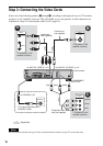
LINE OUT
COMPONENT
VIDEO OUT
VIDEO
S VIDEO
AUDIORL
1
2
Y
P
B
P
R
Y
P
B
P
R
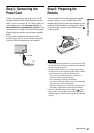
~ AC IN
OUT
SET TOP BOX
CONTROL
CONTROL S IN
G-LINK
VIDEO
AUDIO
INPUT
L
R
LINE OUT
VIDEO
S VIDEO
AUDIORL
1
2
B
A
DIGITAL OUT
COAXIAL
OPTICAL
PCM/DTS/DOLBY DIGITAL
AV amplifier (receiver)
with a decoder
(red)
TV, projector, or AV
amplifier (receiver)
Audio/video
cord (supplied)
: Signal flow
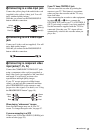
Coaxial digital cord
(not supplied)
to DIGITAL OUT (COAXIAL or
OPTICAL)
to LINE OUT (R-AUDIO-L) 1 or 2
Optical digital cord (not supplied)
Rear (L)
DVD recorder
(white)
(yellow)*
(yellow)
(white)
(red)
[Speakers]
Front (L)
[Speakers]
to coaxial
digital input
Rear (R)
Front (R)
Subwoofer
or
Center
* The yellow plug is used for video signals (page 17).
to optical
digital input
,continued