


Acutime 2000 Synchronization Kit User Guide 4-7
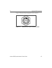
4 Acutime 2000 Connections
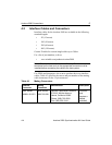
4.3 Connection Instructions
This section provides detailed information for connecting the
Acutime 2000's power, timing pulse and data packet lines.
4.3.1 Power Connection (Red and Black Wires)
The red wire (Acutime 2000 pin #1) and black wire (Acutime 2000
pin #9) in the interface cable support the power and ground
connections, respectively. The Acutime 2000 features a switching DC
power supply, which accepts from 8 to 36 volts. The Acutime 2000 is
protected against reverse polarity and brief over-voltage conditions;
however, sustained over-voltage conditions can cause
permanent damage.
#
Warning – Voltages exceeding 36 volts can cause permanent
damage to the Acutime 2000's power supply.
The typical power consumption of the Acutime 2000 at an input
voltage of 12 volts is 110 milliAmps, or 1.3 watts.
!
Note – The Acutime 2000 requires a minimum of 8 volts at the
interface connector. When specifying the supply voltage, line losses
in the interface cable must be considered. To account for line loss, the
supply voltage may need to exceed 8 volts to satisfy the minimum
voltage at the Acutime 2000.
4.3.2 Timing Pulse Connections
The Acutime 2000 outputs a timing pulse for use in timing and
synchronization applications. The timing pulse is generated using an
RS-422 line driver circuit (pins #11 and #12). The leading edge of the
PPS output pulse is synchronized to UTC. The width of the pulse's
leading edge is 20 nanoseconds or less. The exact width and shape of
the pulse depends on the distributed capacitance in the interface
cable.