


5-8 Acutime 2000 Synchronization Kit User Guide
System Operation
5
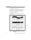
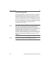
Figure 5-2 illustrates the result of removing the quantization error
from the PPS output in a user system.
The top plot shows the offset of the PPS output pulse relative to a
stable standard such as a Cesium atomic clock. The quantization error
is responsible for the jagged appearance of the waveform.
The middle plot shows the quantization error as reported by the
Acutime 20000 in packet 0x8F-AC.
The bottom plot is the result of subtracting the quantization error
from the PPS offset.
Figure 5-2 Removing the Quantization Error from the
PPS Output
0 100 200 300 400 500
Time (seconds)
-100
-50
0
50
100
PPS Offset (ns)
Quantization Error (ns)
Corrected PPS Offset (ns)
-100
-50
0
50
100
-100
-50
0
50
100
0 100 200 300 400 500
Time (seconds)
0 100 200 300 400 500
Time (seconds)