58-EN
Installation and Connections
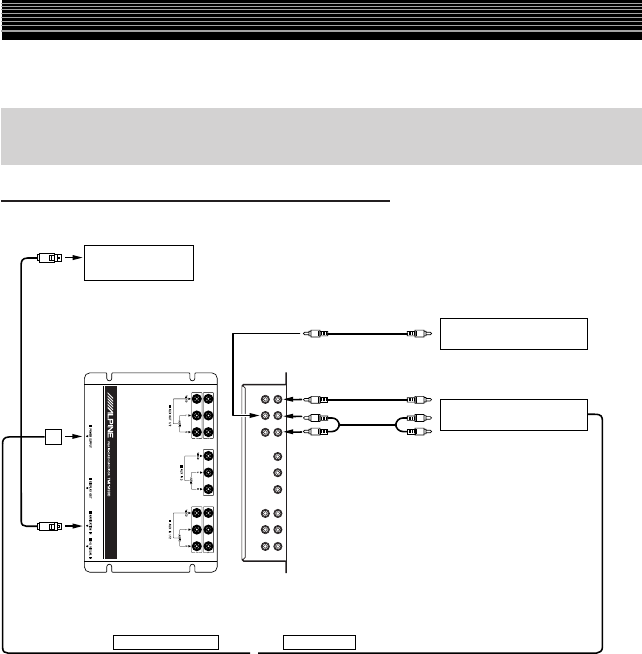
When Connecting External Equipment (If an IONBUS Compatible
Head Unit is not connected)
TMI-M990
AV-Interface unit
1
3
2
5
6
6
7
REMOTE IN (AUX2) REMOTE OUT
4
To Audio Input terminal
To Video Input terminal
When the System Switch is set to “STANDALONE”
1
RGB Cable (Included with NVE-N852, not included with NVE-N871A)
2
Power Supply Connector
3
RGB Input Terminal
Connect this to the RGB output terminal of the Navigation System.
4
AUX Audio Output (AUX1) (L) Terminal
When the System Switch is set to STANDALONE:
AUX1 Audio Output Terminal is used as the audio output for the main unit.
A separately sold Amplifier Speaker (KAX-551N) is required if using this unit by itself.
There is no output from the AUX1 Video Output Terminal.
5
AUX Video/Audio Output (AUX2) Terminal
6
RCA Extension Cable (Sold separately)
7
Remote Control Input Lead (White/Brown)
Navigation system
(Sold Separately)
Amplified Speaker
(Sold Separately)
Rear monitor 2
(Sold Separately)
To Audio Input terminal
(White/Brown)
(White/Brown)
NVE-N852A/NVE-N871A
• When the NVA-N751AS is connected for the Navigation System, use the RGB conversion cable
KWE-503N (Sold separately).
KAX-551N
System Example


