


AVerMedia LX5000 User’s Manual
13
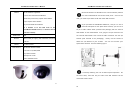
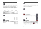
Cameras need to be installed according to the numerical order displayed
on the diagrams above for each model. With the LX5000, cameras
will be installed from top to bottom beginning with the left-most
column.
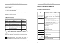
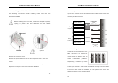
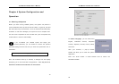
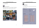
2.4 Connecting External Inputs/Outputs Control Devices
Each system and kit comes with four External I/O Boxes and D-type 15-
pin connector cables enabling you to connect sensor inputs and relay
outputs. The pin signals and specifications for the external I/O Box and
the D-type 15-pin connectors are described below.
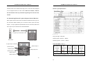
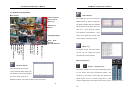
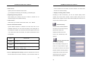
D-type 15-pin Connector Cable
External I/O Box
IN 1
IN 2
IN 3
IN 4
Video Card
External I/O Box
Relay Outputs 3
Sensor Input 3
Relay Output 2
Sensor Input 2
Sensor Input 1
Relay Output 1
D-type 15-pin connector
Sensor Input 4
AVerMedia LX5000 User’s Manual
14
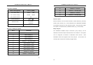
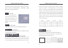
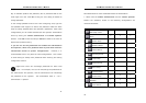
Sensor Input Specification
Relay Output Specification
Surge strength: 1500 VAC
Nominal power: 200mw ~ 360mw
Operating power: 110mw ~ 200mw
COIL RATINGS (at 20
o
C )
Coil Nominal
Voltage
(VDC)
Coil
Resistance
( 10% )
Pick-up
Voltage
(VDC)
Drop-Out
Voltage
(VDC)
Nominal
Current
(mA)
5 125 3.75 0.5 40
* Max Continuous Voltage at 20
o
C : 110% of Coil Nominal Voltage