


Barco - RHDM-1701 - Maintenance Manual ______________________________________________ 31
Removal and reinstallation of electronic boards
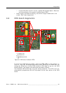
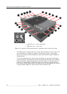
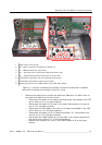
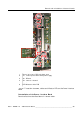
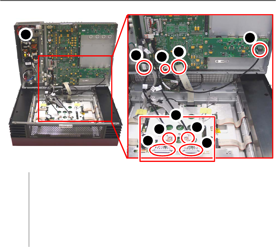
Figure 11: Location of cables that connect the electronic boards in the back
cover with the electronic boards in the front cover.
• Remove the cables that connect the electronic boards in the back cover to
the electronic boards in the front cover
3 Disconnect the cable of the power interface board connected to the LED
driver board (n°2 in the figure above)
3 Disconnect the cable of the main (Iris) board connected to the control
box (n°3 in the figure above)
3 Disconnect the flat cable of the main (Iris) board connected to the LED
driver board (n°4 in the figure above)
3 Disconnect the cable of the I/O board connector J11 connected to the
control box (n°5 in the figure above)
3 Disconnect the LVDS cables (2x) of the main (Iris) board connected to
the panel driver board (n°7 in the figure above).
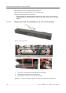
3 Remove the clamps (2x) that fix the LVDS cables (n°8 in the figure
above).
1
2
3
4
5
6
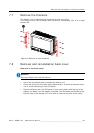
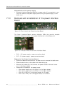
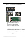
Open cover from the top
J8 - Power connection to LED driver board (J1)
J7 - USB connection to control box
J11 - flat cable from Iris board to LED driver board (J8)
J11 - Communication board connector to control box
5
6
8
8
7
7
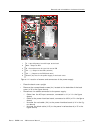
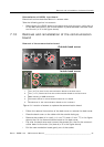
LVDS cable connection area on the panel driver board
Screws (2x) that fix the LVDS cables to the LED driver board
LVDS cable connection to panel driver board
7
8
1
2
3
4