


48 ______________________________________________ Barco - RHDM-1701 - Maintenance Manual
Table of contents
6.5 Power diagnostics ........................................................................... 22
6.6 IRIS board diagnostics..................................................................... 23
6.7 Light diagnostics ............................................................................. 24
6.8 Image diagnostics........................................................................... 24
6.9 Communication diagnostics .............................................................. 24
6.10 Color diagnostics........................................................................... 25
7 Removal and reinstallation of electronic boards ................................... 27
7.1 Service levels ................................................................................. 27
7.2 Module replacements (level 2 and level 3) .......................................... 27
7.3 Module replacements (level 4) .......................................................... 28
7.4 Spare part kits (level 2 and level 3)................................................... 28
7.5 Removal and installation precautions ................................................. 28
7.6 Required tools ................................................................................ 28
7.7 Remove the brackets....................................................................... 29
7.8 Removal and reinstallation back cover ............................................... 29
7.9 Removal and reinstallation of the power supply ................................... 32
7.10 Removal and reinstallation of the power interface board ..................... 34
7.11 Removal and reinstallation of HDSDI board....................................... 36
7.12 Removal and reinstallation of the communication board...................... 37
7.13 Removal and reinstallation of the control box .................................... 38
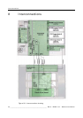
8 Interconnections ............................................................................. 40
9 Adjustments................................................................................... 41
10 Maintenance ................................................................................. 42
10.1 Cleaning precautions ..................................................................... 42
10.2 Cleaning instructions (for CIVIL)...................................................... 42
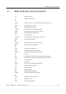
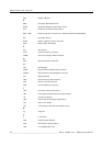
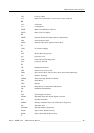
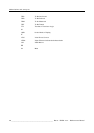
11 Abbreviations and acronyms ........................................................... 43
12.1 List of figures
Figure 1: Front cover – module overview .................................................................... 15
Figure 2: Back cover – module overview .................................................................... 16
Figure 3: Hardware tree RHDM-1701 ......................................................................... 17
Figure 4: Software tree RHDM-1701 .......................................................................... 18
Figure 5: “No power” fault finding tree ....................................................................... 20
Figure 6: “Nothing observed on the screen” fault finding tree ........................................ 21
Figure 7: “Verify input signal” fault finding tree ........................................................... 22
Figure 8: IRIS board indicator LEDs ........................................................................... 23
Figure 9: Removal of rack brackets ............................................................................ 29
Figure 10: Location of the screws that fix the back cover to the front cover ..................... 30
Figure 11: Location of cables that connect the electronic boards in the back cover with the elec-
tronic boards in the front cover. ................................................................................. 31
Figure 12: Correct clamping of the LVDS cables .......................................................... 32
Figure 13: Top view of the power supply .................................................................... 32
Figure 14: Location of screws and connectors of the power supply ................................. 33
Figure 15: Front view of the Power Interface Board ...................................................... 34
Figure 16: Indicator LEDs on the Power Interface Board ............................................... 34
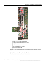
Figure 17: Location of screws, cables and indicator LEDs on the Power Interface Board .... 35
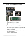
Figure 18: Location of screws to remove/mount the HDSDI input board .......................... 36
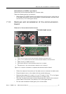
Figure 19: Location of screws to replace the communication board ................................. 37
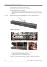
Figure 20: Control box ............................................................................................. 38
Figure 21: Location of screws, cables to remove or install the control box ....................... 38