


Barco - RHDM-1701 - Maintenance Manual ______________________________________________ 33
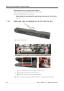
Removal and reinstallation of electronic boards
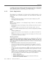
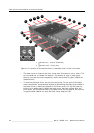
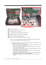
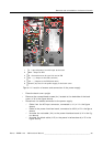
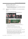
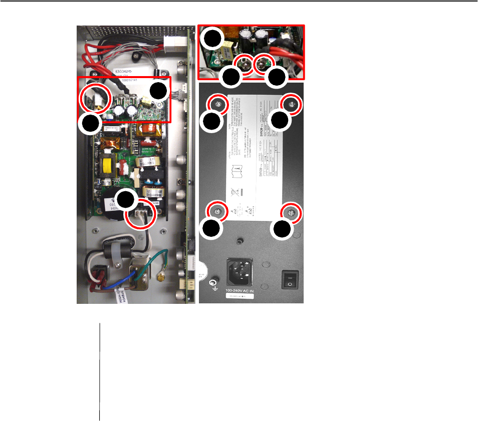
Figure 14: Location of screws and connectors of the power supply
• Place the back cover upright
• Remove the crossed head screws (4x) located at the backside of the back
cover (n°6 in the figure above).
• Disconnect the cables connected to the power supply:
3 Cable from the AC input connector, connected to J1 (n°1 in the figure
above)
3 Cable to the power interface board, connected to J204 (n°2 in the figure
above)
3 Unscrew the red cable (J14) to the power interface board (n°4 in the fig-
ure above)
3 Unscrew the black cable (J15) to the power interface board (n°5 in the
figure above)
1
2
3
4
5
J1 - Input AC power from AC input at the back
J3 - Connection area J14 and J15 to the PIB
J204 - Output to PIB
3
J14 - (+) Output to the PIB (red wire)
J15 - (-) Output to the PIB (black wire)
6
Screws (4x) that fix the power supply to the back cover
4
5
6
6
6
6
2
3
1