


34 ______________________________________________ Barco - RHDM-1701 - Maintenance Manual
Removal and reinstallation of electronic boards
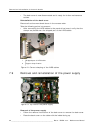
Reinstallation of the power supply
• Execute all actions described above in reverse order. It is convenient to con-
nect the cables to the power supply before fixing the power supply to the
back cover.
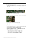
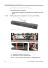
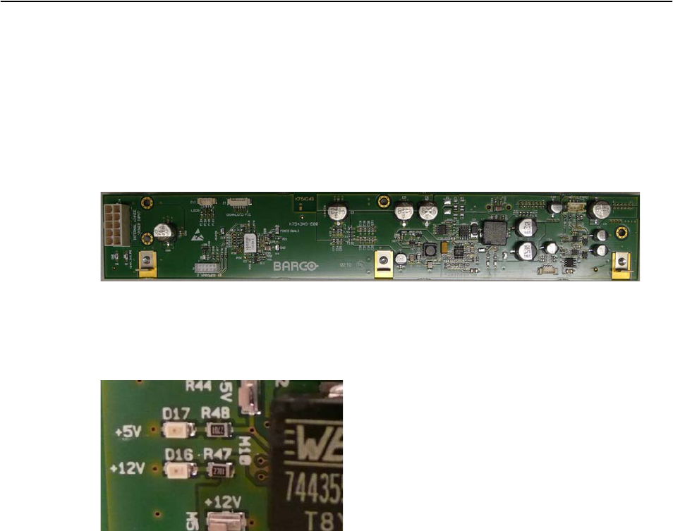
7.10 Removal and reinstallation of the power interface
board
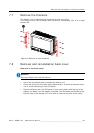
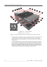
Figure 15: Front view of the Power Interface Board
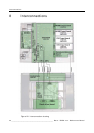
The Power Interface Board contains indicator LEDs that provide valuable
information about the status of the power distribution to the display unit.
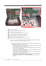
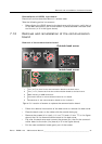
Figure 16: Indicator LEDs on the Power Interface Board
• D16 – 12 V power supply: power conversion check
• D17 – 5 V power supply: power conversion check
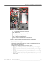
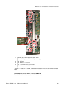
Removal of the Power Interface Board
• Follow the removal instructions of the back cover to remove the back cover.
• Place the back cover on the table with inside facing up.
• Remove the screws (3x) that connect the power board to the back cover
(n°1 in the figure below)
• Disconnect the cables on the power board:
3 From power supply to J4 on PIB (n°2 in the figure below)
3 From power supply to J6 on PIB (n°3 in the figure below)
3 From J9 on PIB (n°4 in the figure below) to Iris board
3 From J10 on PIB (n°5 in the figure below) to Iris board