


Barco - RHDM-1701 - Maintenance Manual ______________________________________________ 37
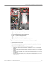
Removal and reinstallation of electronic boards
Reinstallation of HDSDI input board
Execute all actions described above in reverse order.
Take the following points into account:
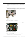
• Before fixing the HDSDI board to the back cover with the nuts, verify that at
all the BNC connectors, the crinkle washer is placed between the back cover
and the nut (n°3 in the figure above).
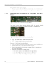
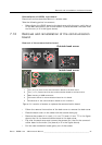
7.12 Removal and reinstallation of the communication
board
Removal of the communication board
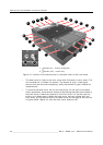
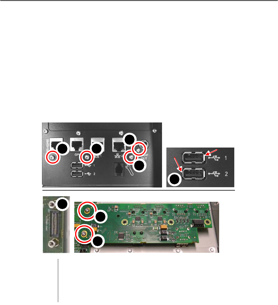
Figure 19: Location of screws to replace the communication board
• Follow the removal instructions of the back cover to remove the back cover.
• Place the back cover on the table with the outside facing up.
• Remove the screws (4 in total) (n°1 torx T10 and n°2 torx T7, in the figure
above) that fix the communication board to the back cover.
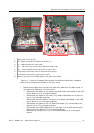
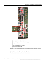
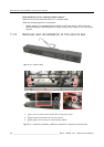
• Flip-over the back cover and remove the screws (2x) that fix the communi-
cation board to the main (Iris) board (n°5 in the figure above).
• Pull the communication board gently out of the socket.
1
2
3
4
5
Torx (3x T10) that fix the communication board to the back cover
Torx (1x T7) screw that fixes the communication board to the back cover
Metal housing of USB connectors
Connector socket for communication board on Iris board
Screws that fix the communication board to the Iris board
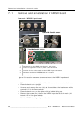
Outside back cover
Inside back cover
1
1
1
3
4
5
2
5