f
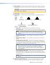
CD/DVD drive — Insert any compatible CD or DVD into this drive. This drive is used for
system updates or software installation.
g
3.5 inch floppy drive — This drive accepts 3.5 inch floppy disks.
Rear Panel Features
NOTE: Some features listed in this user guide may not be available on all units. This will
not affect the overall functionality of the VNM Recorder.
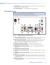
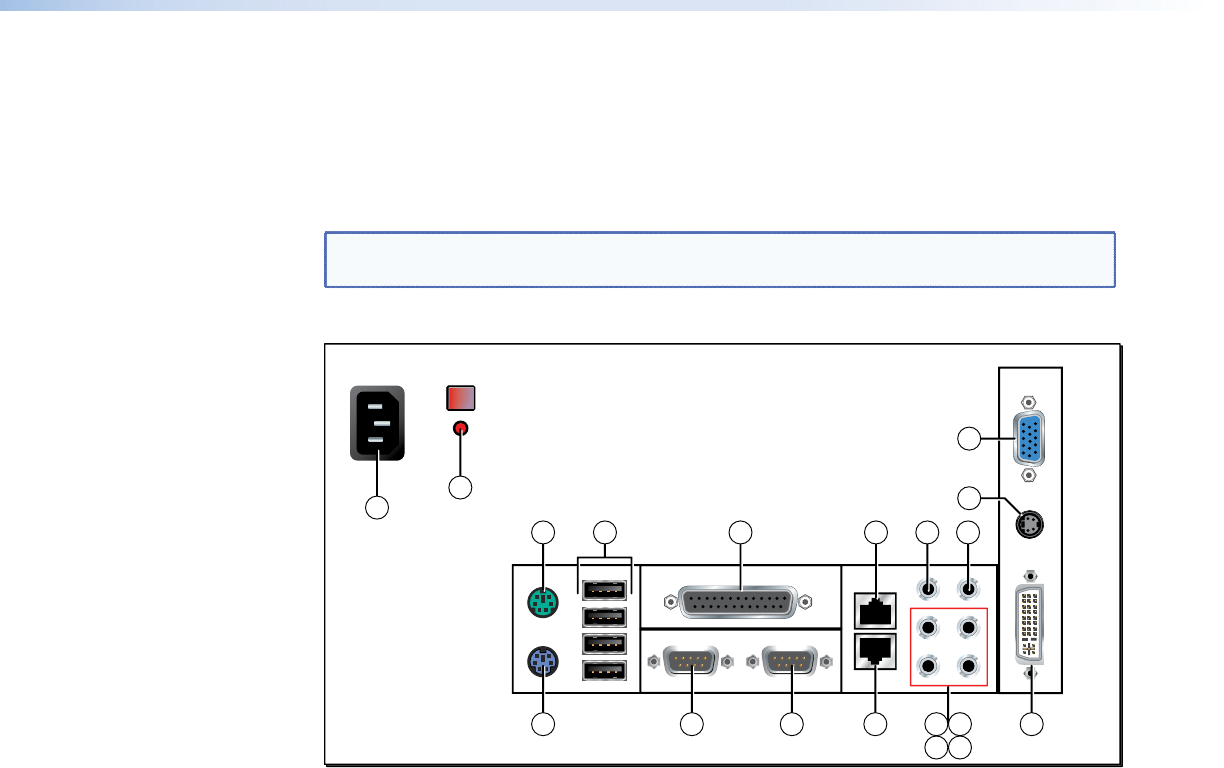
The rear panel connections of the VNM Recorder are shown in figure 7.
17
18
4
1
2
7 8 1910 13 14
15 16
3 6 95 11 12
Figure 7. VNM Recorder Rear Panel Connections
a
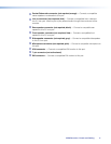
Power input (IEC connector) — Plug a standard IEC power cord into this connector
to connect the recorder to a 100 to 240 VAC, 50 Hz or 60 Hz power source.
b
Alarm Reset button and LED — When the recorder overheats or when a hard drive
fails, an audible alarm is activated and the LED turns on to indicate that there is a
problem with the device. Press this button to turn the alarm off.
c
PS/2 mouse connector (optional) — Connect a PS/2 mouse to this port.
d
PS/2 keyboard connector (optional) — Connect a PS/2 keyboard to this port.
e
USB (Universal Serial Bus) connectors — Insert any compatible USB device into
these ports.
f
Parallel/Printer connector (not used)
g
COM1 serial connector (not required) — Connect a compatible device to this 9‑pin
serial port.
h
COM2 serial connector (not required) — Connect a compatible device to this 9‑pin
serial port.
i
Ethernet connector (eth0) — Connect a RJ‑45 cable to this port. This port connects
to a primary network and is the default network port that should be used to connect to
a VN‑Matrix network.
j
Ethernet connector (eth1) — Connect a RJ‑45 cable to this port. This port connects
to a secondary network.
VNM Recorder • Panels and Cabling 10


