


Garmin G1000 Cockpit Reference Guide for the Columbia 350/400
2-6
SECTION 2
FLIGHT INSTRUMENTS
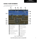
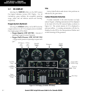
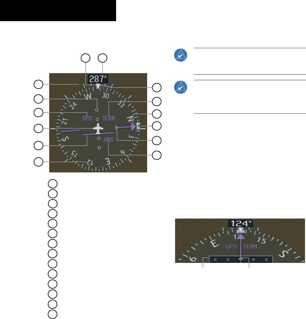
2.7 HORIZONTAL SITUATION INDICATOR
(HSI)
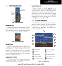
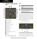
Figure 2-12 Horizontal Situation Indicator (360˚)
8
14
9
6
5
4
3
2
1
7
13
12
11
10
Heading Bug
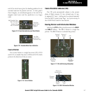
2
3
6
4
5
7
1
Turn Rate Indicator
Navigation Source
Course Deviation Indicator
TO/FROM Indicator
Course Pointer
Rotating Compass Rose
11
10
12
13
14
9
8
OBS Mode
Lateral Deviation Scale
Flight Phase
Aircraft Symbol
Lubber Line
Heading
Turn Rate and Heading Trend Vector
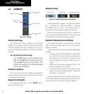
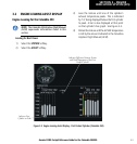
Arc HSI
NOTE: When the Arc HSI is displayed the BRG1
and BRG2 Information Windows and pointers are
disabled.
NOTE: If the pilot makes a heading change
greater than 105˚ with respect to the course, the
CDI switches to the opposite side of the deviation
scale and displays reverse sensing.
The Arc HSI is a 140˚ expanded section of the compass
rose. The Arc contains a Course Pointer arrow, the
TO/FROM indicator, a sliding deviation indicator (the
TO/FROM and sliding deviation indicators are one and
the same), and a deviation scale. Upon station passage,
the TO/FROM indicator flips and points to the tail of
the aircraft, just like the conventional TO/FROM flag.
Depending on the navigation source, the CDI on the Arc
HSI can appear in two different ways:
• GPS, OBS, VOR – Arrowhead
• Localizer – Diamond
Lateral
Deviation
Scale
Course Deviation and
TO/FROM Indicator
Figure 2-13 Arc HSI
Turn Rate Indicator and Heading Trend Vector
Tick marks to the left and right of the lubber line
denote half-standard and standard turn rates. A magenta
turn rate trend vector shows the current turn rate. The