


04/08 UDC3200 Universal Digital Controller Operator Manual 5
2 Installation
2.1 Pre-installation Information
If the controller has not been removed from its shipping carton, inspect the carton for
damage then remove the controller.
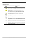
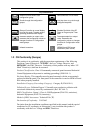
• Inspect the unit for any obvious shipping damage and report any damage due to
transit to the carrier.
• Make sure a bag containing mounting hardware is included in the carton with the
controller.
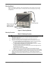
• Check that the model number shown on the inside of the case agrees with what
you have ordered.
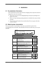
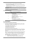
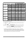
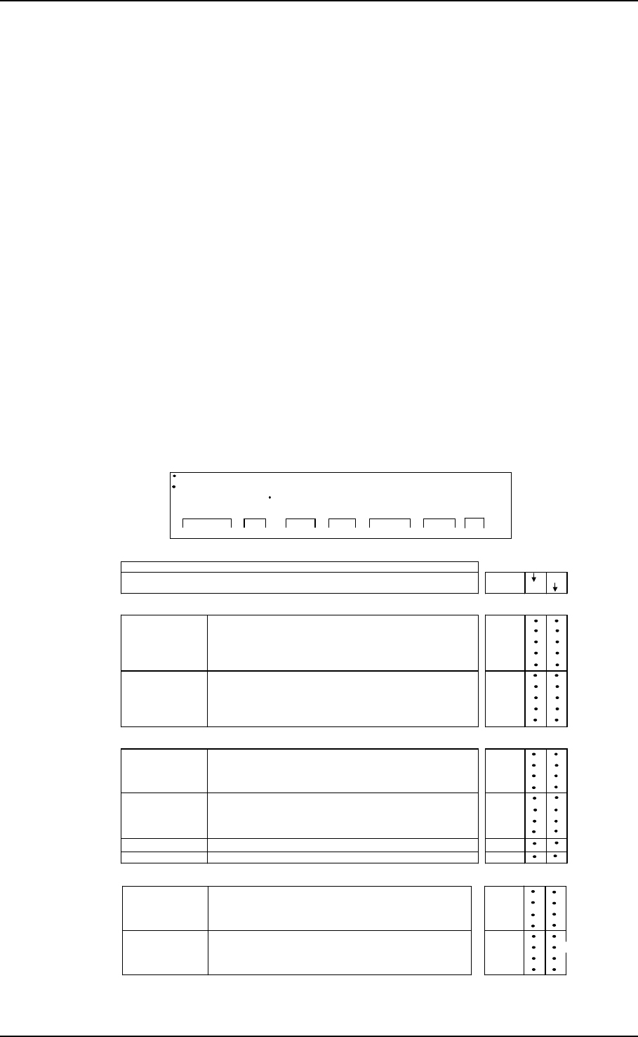
2.2 Model Number Interpretation
Write your controller’s model number in the spaces provided below and circle the
corresponding items in each table. This information will also be useful when you wire your
controller.
Instructions
Select the desired key number. The arrow to the right marks the selection available.
Make the desired selections from Tables I through VI using the column below the
proper arrow. A dot ( ) denotes availability.
Key Number
-- - -
_
_ _ _
_
-
_
_
_ _ _ _
_
_
_
I
_
_
_
IIIII IV
_
_
V
_
_ _
_
VI
KEY NUMBER - UDC3200 Single Loop Controller
Selection
Digital Controller for use with 90 to 264Vac Power DC3200
Digital Controller for use with 24Vac/dc Power DC3201
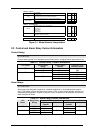
TABLE I - Specify Control Output and/or Alarms
TABLE II - Communications and Software Selections
0 _ _ _
1 _ _ _
2 _ _ _
3 _ _ _
_ 0 _ _
_ A _ _
_ B _ _
_ C _ _
No Selection
_ _ 0 _
_ _ _ R
C _
E _
Math Option
Set Point Programming (1 Program, 12 Segments)
Set Point Programming Plus Math
Current Output (4 to 20ma, 0 to 20 ma)
T _
R _
_ E
_ A
No Additional Outputs or Alarms
Output #1
Software Selections
Standard Functions, Includes Accutune
Open Collector Plus Alarm 1 (5 Amp Form C Relay)
_ T
Output #2 and Alarm
#1 or Alarms 1 and 2
_ B
One Alarm Relay Only
Availability
Infrared Interface Included (Can be used with a Pocket PC)
_ 0
E-M Relay (5 Amp Form C) Plus Alarm 1 (5 Amp Form C Relay)
Solid State Relay (1 Amp) Plus Alarm 1 (5 Amp Form C Relay)
Electro Mechanical Relay (5 Amp Form C)
Solid State Relay (1 Amp)
None
A _
Description
Infrared interface
Reserved
Open Collector transistor output
Dual 2 Amp Relays (Both are Form A) (Heat/Cool Applications)
Communications
Auxiliary Output/Digital Inputs (1 Aux and 1 DI or 2 DI)
RS-485 Modbus Plus Auxiliary Output/Digital Inputs
10
Base-T Ethernet (Modbus RTU) Plus Auxiliary Output/Digital Inputs
TABLE III - Input 1 can be changed in the field using external resistors
1 _ _
2 _ _
3 _ _
Carbon, Oxygen or Dewpoint (Requires Input 2)
1 6 0
_ 00
_ 10
_ 20
Slidewire Input (Requires two Relay Outputs) _ 40
None
TC, RTD, mV, 0-5V, 1-5V, 0-20mA, 4-20mA
TC, RTD, mV, 0-5V, 1-5V, 0-20mA, 4-20mA
TC, RTD, mV, 0-5V, 1-5V, 0-20mA, 4-20mA, 0-10V
Input 1
Input 2
TC, RTD, mV, 0-5V, 1-5V
TC, RTD, mV, 0-5V, 1-5V, 0-20mA, 4-20mA, 0-10V