


10 UDC3200 Universal Digital Controller Operator Manual 04/08
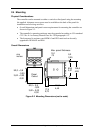
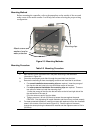
• Separate External Wiring—Separate connecting wires into bundles
(See Permissible Wiring Bundling - Table 2-4) and route the individual bundles
through separate conduit metal trays.
Use Suppression Devices—For additional noise protection, you may want to add
suppression devices at the external source. Appropriate suppression devices are
commercially available.
ATTENTION
For additional noise information, refer to document number 51-52-05-01, How to Apply Digital
Instrumentation in Severe Electrical Noise Environments.
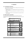
Permissible Wiring Bundling
Table 2-4 Permissible Wiring Bundling
Bundle No. Wire Functions
1
• Line power wiring
• Earth ground wiring
• Line voltage control relay output wiring
• Line voltage alarm wiring
2 Analog signal wire, such as:
• Input signal wire (thermocouple, 4 to 20 mA, etc.)
• 4-20 mA output signal wiring
Digital input signals
3
• Low voltage alarm relay output wiring
• Low voltage wiring to solid state type control circuits
• Low voltage wiring to open collector type control circuits
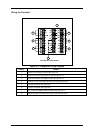
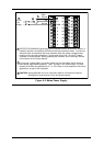
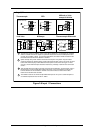
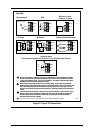
2.6 Wiring Diagrams
Universal Output Functionality and Restrictions
Instruments with multiple outputs can be configured to perform a variety of output
types and alarms. For example, an instrument with a current output and two relays
can be configured to perform any of the following:
1) Current Simplex with two alarm relays;
2) Current Duplex 100% with two alarm relays;
3) Time Simplex with one alarm relay;
4) Time Duplex with no alarm relays; or
5) Three Position Step Control with no alarm relays.
These selections may all be made via the keyboard and by wiring to the appropriate
output terminals; there are no internal jumpers or switches to change. This flexibility
allows a customer to stock a single instrument which is able to handle a variety of
applications.
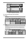
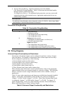
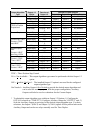
Table 2-5 shows what control types and alarms are available based upon the installed
outputs. In this table, when Duplex Control and Reverse Action are configured,
“Output 1” is HEAT while “Output 2” is COOL. When Three Position Step Control
is configured, “Output 1” is OPEN while “Output 2” is CLOSE. The Output 1/2
option “Single Relay” can be any of the following selections: Electro-Mechanical
Relay, Solid-State Relay or Open Collector Output.
Table 2-5 Universal Output Functionality and Restrictions