


04/08 UDC3200 Universal Digital Controller Operator Manual 69
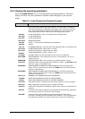
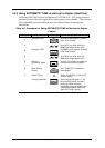
4.4.3 Diagnostic Messages
The UDC3200 performs background tests to verify data and memory integrity. If
there is a malfunction, a diagnostic message will be shown on the lower display. In
the case of more than one simultaneous malfunction, only the highest priority
diagnostic message will be displayed. Table 4-4 shows the error messages in order by
priority.
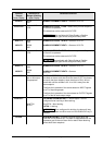
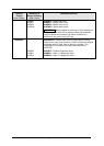
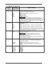
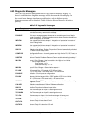
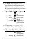
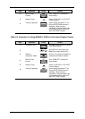
Table 4-4 Diagnostic Messages
Prompt Description
EE FAIL
Unable to write to nonvolatile memory. A subsequent successful write to
nonvolatile memory removes this message.
FAILSAFE
This error message appears whenever the controller goes into a failsafe
mode of operation. Failsafe operation occurs when an analog input fails or
when configuration is corrupted.
INP1FAIL
Two consecutive failures of input 1 integration or input value is outside of
Out-of-Range limits.
INP2FAIL
Two consecutive failures of input 2 integration or input value is outside of
Out-of-Range limits.
SW FAIL
Slidewire input failure. Position Proportional Control automatically switched
to Three Position Step Control.
CONF ERR
Configuration Errors—Low limit greater than high limit for PV, SP, Reset, or
Output.
SOOTING
Carbon Potential Problem—Percent Carbon outside of “sooting boundary.”
IN1 RNG
Input 1 Out-of-Range—Input is outside of the High or Low Limits.
Out-of-range criteria:
Linear range: ± 10 %
Characterized range: ± 1 %
IN2 RNG
Input 2 Out-of-Range—Same criteria as Input 1.
PV LIMIT
PV beyond limits—PV outside of PV Hi/Low Limits.
PV = (PV source x PV source ratio) + PV source bias
FAILSAFE
Failsafe—Check inputs or configuration.
RV LIMIT
Remote Variable beyond limits—RSP outside of SP Hi/Low Limits.
RV = (RV source x RV source ratio) + RV source bias
SEG ERR
Segment Error—SP Program starting segment number is less than ending
segment number.
CAL MTR
Slidewire not calibrated. Perform Slidewire calibration.
SW FAIL
Position Proportional slidewire input failure.
TC1 WARN
The Thermocouple on Input 1 is starting to burnout.
TC2 WARN
The Thermocouple on Input 2 is starting to burnout.
TC1 FAIL
Thermocouple on Input 1 is in imminent danger of burning out.
TC2 FAIL
Thermocouple on Input 2 is in imminent danger of burning out.
OUT1FAIL
Current Output is less than 3.5 mA.
OUT2FAIL
Current Output 2 is less than 3.5 mA.