


04/08 UDC3200 Universal Digital Controller Operator Manual 61
Function
Prompt
Lower Display
Selections or
Range of Setting
Upper Display
Parameter Definition
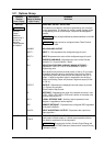
A1S2 EV
BEGIN
END
ALARM 1 SEGMENT EVENT 2—Same as A1S1 EV.
A2S1TYPE
Same as A1S1
TYPE
ALARM 2 SETPOINT 1 TYPE—Select what you want Setpoint 1
of Alarm 2 to represent.
The selections are the same as A1S1TYPE.
ATTENTION Not available with Relay Duplex or Position
Proportional output types unless using Dual Relay PWA.
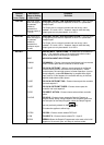
A2S1 H L
HIGH
LOW
ALARM 2 SETPOINT 1 STATE—Same as A1S1 H L.
A2S1 EV
BEGIN
END
ALARM 2 SEGMENT EVENT 1—Same as A1S1 EV.
A2S2TYPE
Same as A1S1
TYPE
ALARM 2 SETPOINT 2 TYPE—Select what you want Setpoint 2
of Alarm 2 to represent.
The selections are the same as A1S1TYPE.
ATTENTION Not applicable with Relay Duplex or Position
Proportional output types unless using Dual Relay PWA.
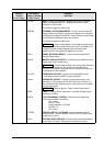
A2S2 H L
HIGH
LOW
ALARM 2 SETPOINT 2 STATE—Same as A1S1 H L.
A2S2 EV
BEGIN
END
ALARM 2 SEGMENT EVENT 2—Same as
A1S1 EV.
ALHYST
0.0 to 100.0 % of
span or full output
as appropriate
ALARM HYSTERESIS—A single adjustable hysteresis is
provided on alarms such that when the alarm is OFF it activates
at exactly the alarm setpoint; when the alarm is ON, it will not
deactivate until the variable is 0.0 % to 100 % away from the
alarm setpoint.
Configure the hysteresis of the alarms based on INPUT signals
as a % of input range span.
Configure the hysteresis of the alarm based on OUTPUT signals
as a % of the full scale output range.
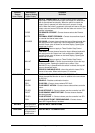
ALM OUT1
LATCHING ALARM OUTPUT 1—Alarm output 1 can be
configured to be Latching or Non-latching.
NoLATCH
LATCH
NoLATCH —Non-latching
LATCH—Latching
ATTENTION When configured for latching, the alarm will stay
active after the alarm condition ends until the RUN/HOLD key is
pressed.
BLOCK
ALARM BLOCKING—Prevents nuisance alarms when the
controller is first powered up. The alarm is suppressed until the
parameter gets to the non-alarm limit or band. Alarm blocking
affects both alarm setpoints.