


04/08 UDC3200 Universal Digital Controller Operator Manual 67
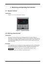
4.4 Monitoring Your Controller
4.4.1 Annunciators
The following annunciator functions have been provided to help monitor the
controller:
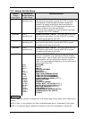
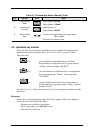
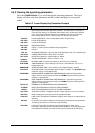
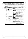
Table 4-2 Annunciators
Annunciator Indication
ALM 1 2
A visual indication of each alarm
Blinking 1 indicates an alarm latched condition. The blinking will
continue even after the alarm condition ends until it is acknowledged by
pressing the RUN/HOLD key.
OUT 1 2
A visual indication of the control relays
DI 1 2
A visual indication of each Digital Input
A or MAN
A visual indication of the mode of the controller)
A—Automatic Mode
MAN—Manual Mode
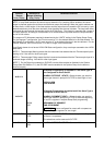
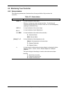
[None], F or C
A visual indication of the temperature units
[None]—No temperature unit annunciator
F—Degrees Fahrenheit
C—Degrees Celsius
n
A visual Lamp to indicate when the lower display is showing the Active
Setpoint (Local 1, Local 2, Local 3, Remote Setpoint or Computer
Setpoint)
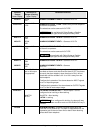
The upper left digit of the display is used to show other annunciator
functions
T—Accutuning in process
C—Computer overide active
O—Output override active