


12 UDC3200 Universal Digital Controller Operator Manual 04/08
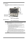
Wiring the Controller
L1
L2/N
4
5
6
7
1
10
11
12
13
14
15
16
17
7
8
9
20
21
22
23
24
25
26
27
18
19
See table for callout details
2
3
4
5
6
8
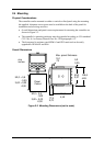
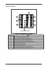
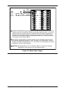
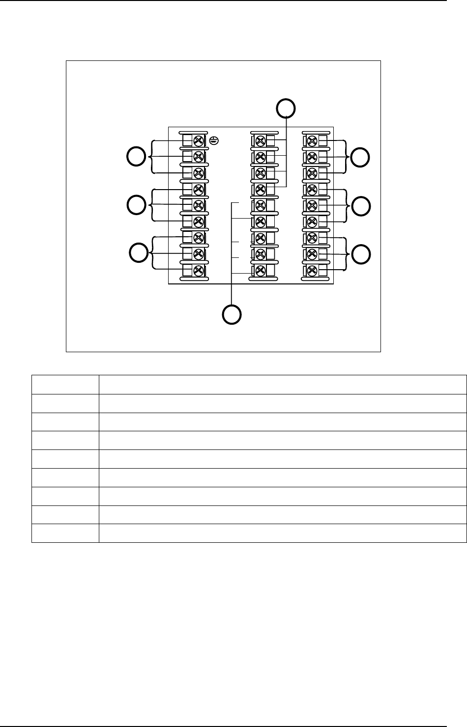
Figure 2-4 Composite Wiring Diagram
Callout Details
1 AC/DC Line Voltage Terminals. See Figure 2-5.
2 Output 3 Terminals. See Figure 2-8 through Figure 2-14.
3 Output 4 Terminals. See Figure 2-8 through Figure 2-14.
4 Outputs 1 and 2 Terminals. See Figure 2-8 through Figure 2-14.
5 Input #2 Terminals. See Figure 2-7.
6 Input #1 Terminals. See Figure 2-6.
7 Aux. Output and Digital Inputs Terminals. See Figure 2-17.
8 Communications Terminals. See Figure 2-15 and Figure 2-16.