


14 UDC3200 Universal Digital Controller Operator Manual 04/08
25
26
27
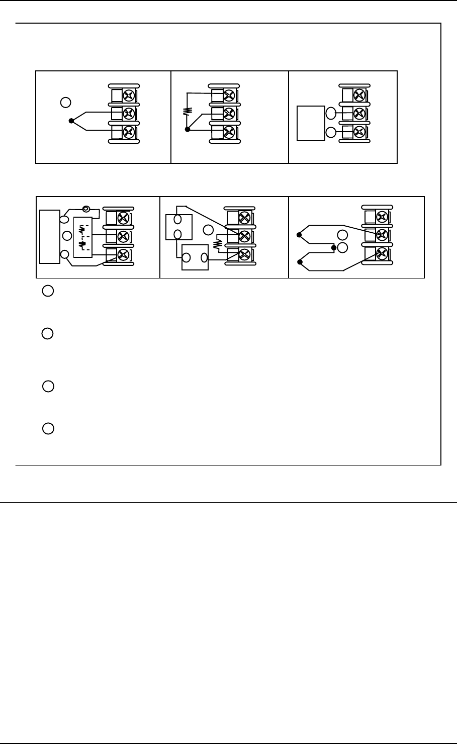
Use Thermocouple
extension wire only
Thermocouple
RTD
Millivolt or Volts
except 0-10 Volts
source
0-10 Volts Milliamps
–
+
+
R
–
1
2
3
–
0–10
Volt
source
+
100K
100K
Power
Supply
–+
Xmitter
+
–
250
Ω
25
26
27
+
R
–
25
26
27
+
R
–
25
26
27
+
R
–
1
25
26
27
+
R
–
1
Input #1
mV or
Volt
source
25
26
27
Use Thermocouple
extension wire only
+
R
–
Thermocouple Differential
+
+
–
–
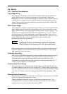
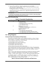
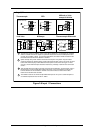
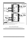
The 250 ohm resistor for milliamp inputs or the voltage divider for 0-10 Volt inputs are supplied
with the controller when those inputs are specified. These items must be installed prior to start
up when the controller is wired. For 0-20 mA applications, the resistor should be located at the
transmitter terminals if Burnout detection is desired.
1
2
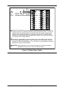
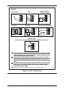
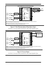
Splice and tape this junction between the two thermocouples. This junction may be located
anywhere between the thermocouples and the instrument terminals, it does not need to be close
to the other thermocouple junctions. Both thermocouples must be of the same type. For best
accuracy, the two thermocouples should be matched or, preferably, made from the same batch
of wire.
2
This controller does not produce a steady current for burnout detection. For that reason, when a
thermocouple is used in parallel with another instrument, it may be desirable to configure the
burnout selection for this controller to “NOFS” and use the burnout current from the other
instrument to also drive this controller.
3
3
4
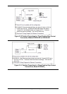
The millivolt values for the Thermocouple Differential Input are for a pair of J thermocouples at
an ambient temperature mean of 450°F / 232°C.
4
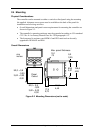
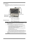
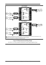
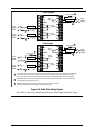
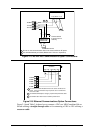
Figure 2-6 Input 1 Connections