


80 UDC3200 Universal Digital Controller Operator Manual 04/08
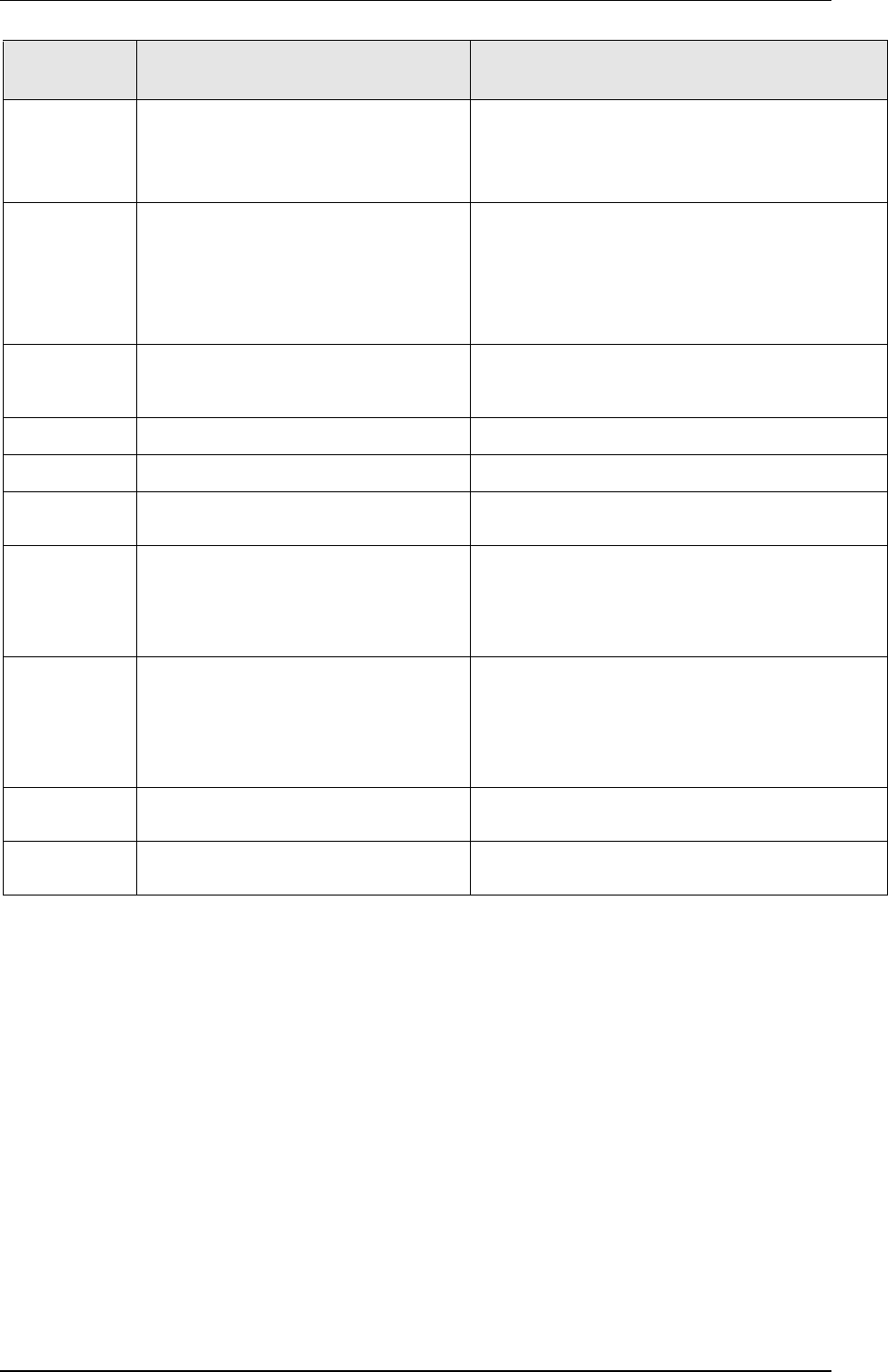
Lower
Display
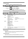
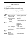
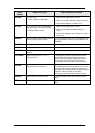
Reason for Failure How to Correct the Problem
PV LIMIT
PV out of range.
PV = INP1 x RATIO1+ INP1 BIAS
1. Make sure the input signal is correct.
2. Make sure the Ratio and Bias settings are correct.
3. Recheck the calibration. Use Bias of 0.0
RV LIMIT
The result of the formula shown below is
beyond the range of the remote variable.
RV = INP2 X RATIO + BIAS
1. Make sure the input signal is correct.
2. Make sure the Ratio2 and Bias2 settings are
correct.
3. Recheck the calibration. Use a Ratio2 of 1.0 and a
Bias2 of 0.0.
SEGERR
Setpoint Program start segment number is
less than ending segment number.
Check SP Program configuration, subsection 3.4 Set
up Group SPPROG function prompts “STRSEG” and
“ENDSEG”.
CAL MTR
Slidewire calibration never performed. Field Calibrate the slidewire.
SW FAIL
Position Proportional slidewire input failure. Check the slidewire.
SOOTING
Percent Carbon falls outside sooting
boundary
Check process for correct operation.
TCx WARN
Thermocouple on Input x (1 or 2) is
starting to burnout.
This diagnostic message means that the controller
has detected that the thermocouple is starting to
burnout. This error message may also be created if
the resistance of the wires used to connect the
thermocouple to the instrument is above 100 ohms.
TCxFAIL
The Thermocouple on Input x (1 or 2) is in
imminent danger of burning out.
This diagnostic message means that the controller
has detected that the thermocouple will soon fail. User
should consider replacing the thermocouple as soon
as possible. This message will also be generated if the
resistance of the wires used to connect the
thermocouple to the instrument is above 180 ohms.
CURFAIL
Current Output is less than 3.5 mA. The current output is open circuit. Check the field
wiring.
AXFAIL
Auxiliary Output is less than 3.5 mA. The auxiliary output is open circuit. Check the field
wiring.