


04/08 UDC3200 Universal Digital Controller Operator Manual 43
Function
Prompt
Lower Display
Selections or
Range of Setting
Upper Display
Parameter Definition
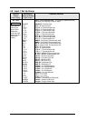
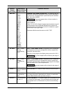
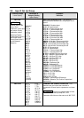
XMITTER
B TC
E TC H
E TC L
J TC H
J TC M
J TC L
K TC H
K TC M
K TC L
NNM H
NNM L
NIC H
NIC L
R TC
S TC
T TC H
T TC L
W TC H
W TC L
100 PT
100 LO
200 PT
500 PT
RAD RH
RAD RI
LINEAR
SQROOT
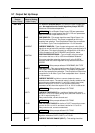
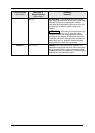
TRANSMITTER CHARACTERIZATION—This selection lets you
instruct the controller to characterize a linear input to represent a
non-linear one. If characterization is performed by the transmitter
itself, then select LINEAR.
ATTENTION Prompt only appears when a linear actuation is
selected at prompt IN1 TYPE.
FOR EXAMPLE:
If input 1 is a 4 to 20 mA signal, but the signal represents a type K
H thermocouple, then configure K TC H and the controller will
characterize the 4 to 20 mA signal so that it is treated as a type K
thermocouple input (high range).
Parameter definitions are the same as in IN1 TYPE.
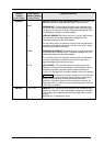
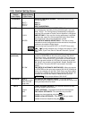
IN1 HIGH
–999. To 9999.
Floating
(in engineering
units)
INPUT 1 HIGH RANGE VALUE in engineering units is displayed
for all inputs but can only be configured for linear or square root
transmitter characterization.
Scale the #1 input signal to the display value you want for 100 %.
ATTENTION The control setpoint will be limited by the range of
units selected here.
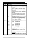
IN1 LOW
–999. To 9999.
Floating
(in engineering
units)
INPUT 1 LOW RANGE VALUE in engineering units is displayed
for all inputs but can only be configured for linear or square root
transmitter characterization. Scale the #1 input signal to the display
value you want for 0 %. See example above.
ATTENTION The control setpoint will be limited by the range of
units selected here.
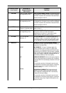
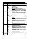
RATIO 1
–20.00 to 20.00
Floats to 3 decimal
places
RATIO ON INPUT 1—Select the Ratio value you want on Input 1.
BIAS IN1
–999. to 9999.
(in engineering
units)
BIAS ON INPUT 1 — Bias is used to compensate the input for drift
of an input value due to deterioration of a sensor, or some other
cause. Select the bias value you want on Input 1.
FILTER 1
0 to 120 seconds
No filter = 0
FILTER FOR INPUT 1—A software digital filter is provided for Input
1 to smooth the input signal. You can configure the first order lag
time constant from 1 to 120 seconds. If you do not want filtering,
enter 0.