


60 UDC3200 Universal Digital Controller Operator Manual 04/08
Function
Prompt
Lower Display
Selections or
Range of Setting
Upper Display
Parameter Definition
regardless of whichever SP is active.
NOTE 4. Loop Break monitors the control loop to determine if it is working. When enabled, the control
output is checked against the minimum and maximum output limit settings. When the output reaches one
of these limits, a timer begins. If the timer expires and the output has not caused the PV to move by a pre-
determined amount, then the alarm activates, thus signalling that the loop is broken. The loop break timer
value must be configured by the operator as the AxSx VAL entry. This value is in seconds with a range of
0 to 3600 seconds. A setting of 0 is equivalent to an instantaneous loop break when the output reaches
one of its limit values.
The amount of PV Movement required is determined by the “UNITS” setting in the Display Setup Group.
For the Degrees F configuration, the PV must move by 3° in the desired direction in the time allowed. For
the Degrees C configuration, the PV must move by 2° in the desired direction in the time allowed. For the
“NONE” selection, the PV must move 1% of the PV range in the time allowed.
Loop Break alarms do not have a HIGH/LOW State configuration, they are always assumed to be a HIGH
state alarm.
NOTE 5. Thermocouple Warning means that the instrument has detected that the Thermocouple Input is
starting to fail. Not valid for other input types.
NOTE 6. Thermocouple Failing means that the instrument has detected that the Thermocouple Input is in
imminent danger of failing. Not valid for other input types.
NOTE 7: For the Digital Input selections, DIG INP1 can be either enabled or disabled in the Options
Group (See Sub-Section
3.11), but DIG INP2 must be enabled in the Options Group for the alarm to
function properly.
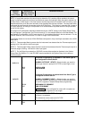
A1S1 H L
If Setpoint Programming is disabled or if the Alarm Type is
not configured for Event On/Off:
ALARM 1 SETPOINT 1 STATE—Select whether you want the
alarm type chosen in prompt A1S1TYPE to alarm High or Low.
HIGH
LOW
HIGH ALARM
LOW ALARM
A1S1 EV
If Setpoint Programming is enabled and if the Alarm Type is
configured for Event On/Off:
ALARM 1 SEGMENT EVENT 1—Select whether you want the
alarm type chosen in prompt A1S1TYPE to alarm the beginning
or end of a segment in setpoint Ramp/Soak programming.
BEGIN
END
BEGINNING OF SEGMENT
END OF SEGMENT
ATTENTION Alarms configured for events will not operate on
Setpoint Program segments of zero length.
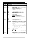
A1S2TYPE
Same as A1S1
TYPE
ALARM 1 SETPOINT 2 TYPE—Select what you want Setpoint 2
of Alarm 1 to represent.
The selections are the same as A1S1TYPE.
A1S2 H L
HIGH
LOW
ALARM 1 SETPOINT 2 STATE—Same as A1S1 H L.