


68 UDC3200 Universal Digital Controller Operator Manual 04/08
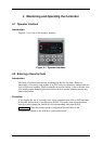
4.4.2 Viewing the operating parameters
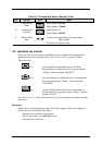
Press the LOWER DISPLAY key to scroll through the operating parameters. The lower
display will show only those parameters and their values that apply to your specific
model.
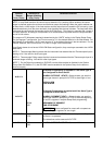
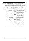
Table 4-3 Lower Display Key Parameter Prompts
Lower Display Description
OUT XX.X
OUTPUT—Output value is shown in percent with one decimal point for all output
types except Three Position Step Control (TPSC). For TPSC, when no slidewire is
connected, this display is an estimated motor position and is shown with no decimal
point. For Position Proportional Control, if the slidewire fails, then the instrument
automatically switches over to TPSC and the OUT display changes with it.
SP XXXX
LOCAL SETPOINT #1—Also current setpoint when using SP Ramp.
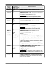
2SP XXXX
LOCAL SETPOINT #2
3SP XXXX
LOCAL SETPOINT #3
RSP XXXX
REMOTE SETPOINT
1IN XXXX
INPUT 1—Used only with combinational input algorithms.
2IN XXXX
INPUT 2
POS XX
SLIDEWIRE POSITION—Used only with TPSC applications that use a slidewire input.
CSP XXXX
COMPUTER SETPOINT—When SP is in override.
DEV XXXX
DEVIATION—Maximum negative display is –999.9.
PIDSET X
TUNING PARAMETER —where X is either 1 or 2.
ET HR.MN
ELAPSED TIME—Time that has elapsed on the Timer in Hours.Minutes.
OTR HR.MN
TIME REMAINING—Time remaining on the Timer in Hours.Minutes. The “O” is a
rotating clock face.
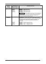
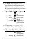
RAMPXXXM
SETPOINT RAMP TIME—Time remaining in the Setpoint Ramp in minutes.
SPN XXXX SETPOINT NOW—Current Setpoint when SP Rate is enabled. The SP XXXX display
shows the “target” or final setpoint value.
XXRAHR.MN
RAMP SEGMENT NUMBER AND TIME REMAINING—Set Point Programming
display. XX is the current segment number and HR.MN is the time remaining for this
segment in Hours.Minutes.
XXSKHR.MN
SOAK SEGMENT NUMBER AND TIME REMAINING— Set Point Programming
display. XX is the current segment number and
HR.MN is the time remaining for this
segment in Hours.Minutes.
RECYC XX
NUMBER OF SP PROGRAM RECYCLES REMAINING
To BEGIN
RESET SP PROGRAM TO START OF FIRST SEGMENT
RERUN
RESET SP PROGRAM TO START OF CURRENT SEGMENT
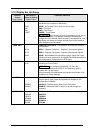
AUX XXXX
AUXILIARY OUTPUT—Displayed only when output algorithm is not Current Duplex.
BIA XXXX
BIAS—Displays the manual reset value for algorithm PD+MR.
TUNE OFF
LIMIT CYCLE TUNING NOT RUNNING—Appears when Accutune is enabled but not
operating.
DO FAST
Limit Cycle Tuning with the objective of producing quarter-damped tuning parameters.
This tuning may result in PV overshoot of the SP setting.
DO SLOW
Limit Cycle Tuning with the objective of producing damped or Dahlin tuning
parameters, depending upon the detected process deadtime. The tuning parameters
calculated by this selection are aimed at reducing PV overshoot of the SP setting.