


Connecting the VP-747 Control Ports
17
17
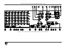
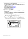
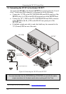
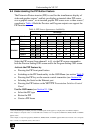
7.2 Connecting the AUDIO CONTROL Port
The Kramer VP-727A Audio Switcher operates in conjunction with the
VP-747. When connected, the audio switcher signals follow the video
signals
1
To connect the VP-747 to the Kramer VP-727A Audio Switcher via the TO
AUDIO UNIT RS-485 port, as illustrated in the example in
.
Figure 7, do the
following:
• Connect the “A” (+) PIN on the AUDIO CONTROL RS-485 rear panel
port of the VP-747 to the A (+) PIN on the RS-485 rear panel port of the
VP-727A unit
• Connect the “B” (-) PIN on the AUDIO CONTROL RS-485 rear panel
port of the VP-747 to the B (-) PIN on the RS-485 rear panel port of the
VP-727A unit
• If shielded twisted pair cable is used, the shield may be connected to the
“G” (Ground) PIN on one of the units
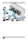
Figure 7: Connecting the VP-727A to the VP-747
1 See the separate VP-727A user manual on our Web site at http://www.kramerelectronics.com