


8
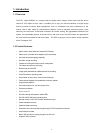
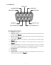
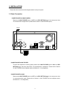
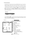
2.3 ALARM In/Out
ALARM IN
ALARM OUT
RECORD IN GROUND
DISK FULL
ALARM RESET
NO CONNECTION NO CONNECTION
SWITCH OUT
12345
6789
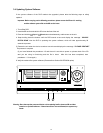
THIS FIGURE IS FROM THE REAR VIEW
1. GROUND: Ground Contact.
2. ALARM OUT (OUTPUT): This is an alarm output trigger. Connect this to external devices such
as buzzers or lights. (
5V
0V(Active)
)
3. DISK FULL (O UTPUT): This is a disk full output trigger. Connect this to external devices such
as buzzers or lights. (
5V
0V(Active)
)
4. ALARM RESET (INPUT): This pin connects to an alarm-clear device for clearing an alarm.
(
5V
0V(Active)
)
5. REC ORD (INPUT): This pin connects to a record trigger device for starting a record.
(
5V
0V(Active)
)
6. SWITCH OUT (OUTPUT): This pin sends out timing signals (falling / negative) to a multiplexer
and connects to a multiplexer’s trigger terminal so the multiplexer can switch to use the same
recording speed as the DVR. (Refer to Section 4.1.1 for multiplexer configuration.)
7. NO CONNECTION
8. NO CONNECTION
9. ALARM IN (INPUT): This is an alarm input which can be programmed in the menu system to
Normally Open or Normally Closed. (
5V
0V(Active)
)