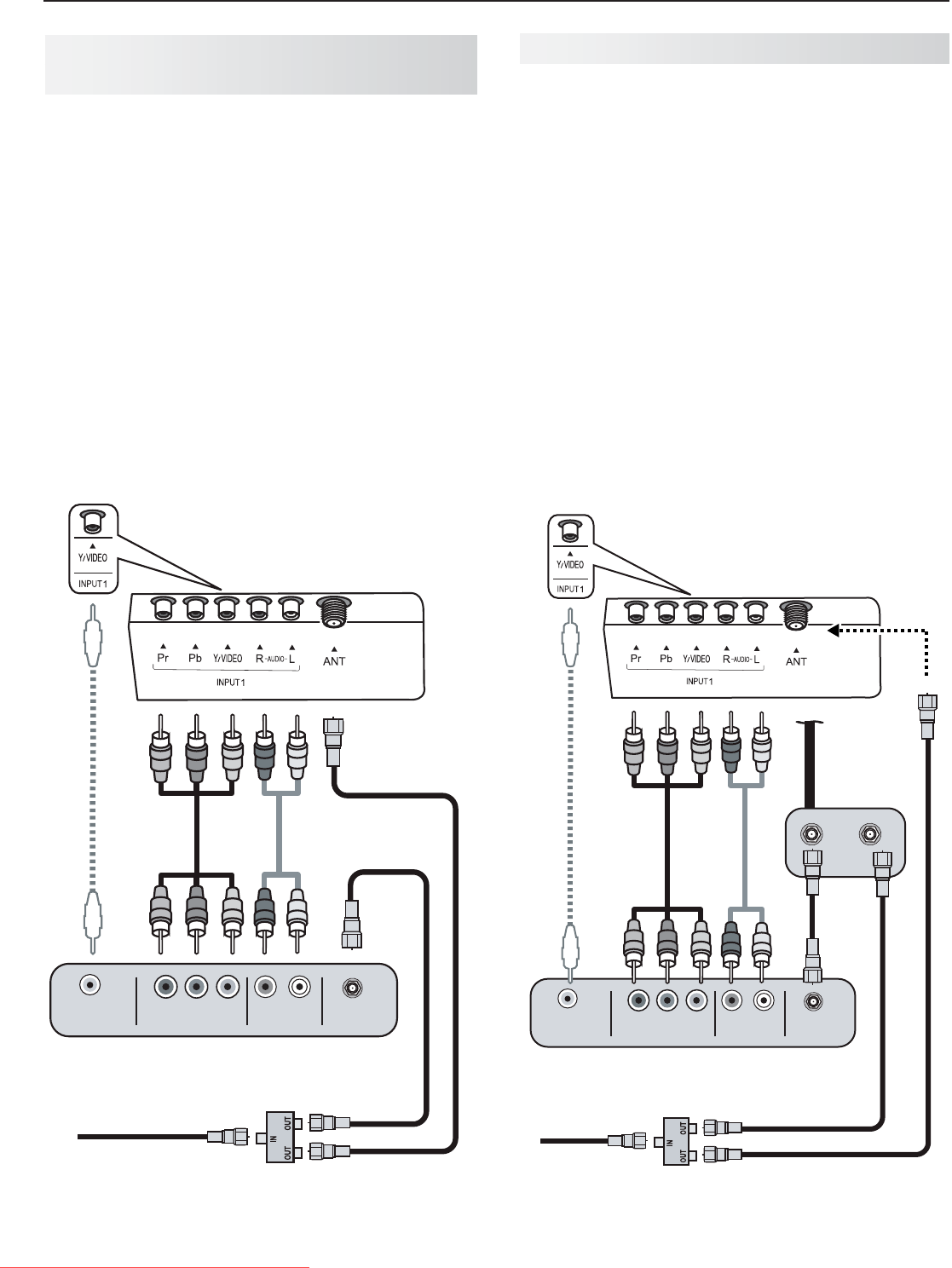
22 2. TV Connections
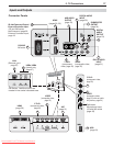
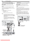
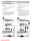
VCR or DVD Recorder to an
Antenna or Wall Outlet Cable
Required:
1. Videocables
1a. Componentvideocables(red/blue/green)
or
1b. Compositevideocable(usuallyyellow)
2. Left/rightanalogaudiocables.
3. Two-wayRFsplitter
4. Twocoaxialcables
Note:
Usecompositevideoonlyifcomponentvideoor•
HDMIareunavailable.ForanHDMIconnection
betweentheTVandrecorder,seepage20.
Ifyourrecordingdevicehasananalog-onlytuner,•
youmustuseadigitalconverterboxtoenable
recordingofdigitalbroadcasts.
AVR AUDIO OUTPUT
R
L
1
2
3
HDMI
AVR
AUDIO
OUTPUT
L
R
Pb
Y/ VIDEO
Pr
Pb
Pr
INPUT 2
INPUT 1
DIGITAL
AUDIO
OUTPUT
DVI/PC
AUDIO
(480i / 480p / 720p / 1080i)
L
R
L
R
INPUT
AUDIO
Y/ VIDEO
3D
GLASSES
EMITTER
ANT
IR-
NetCommand
Output
R
ANT
Y/ VIDEO
AUDIO OUT
COMPOSITE
VIDEO OUT
COMPONENT
VIDEO OUT
LR
ANTENNA
IN
TV
1a.
2.
3.
4.
4.
1b.
or
DVD Recorder or VCR
Incoming cable
RF Splitter
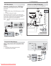
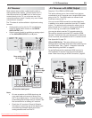
VCR or DVD Recorder to a Cable Box
Required:
. Videocables
1a. Componentvideocables(red/blue/green)
or
1b. Compositevideocable(usuallyyellow)
2. Left/rightanalogaudiocables.
3. Two-wayRFsplitter
4. Threecoaxialcables
5. VideoandaudiocablesrequiredtoconnecttheTV
tothecablebox.
Notes: Usecompositevideoifonlyifcomponentvideo
orHDMIareunavailable.ForanHDMIconnec-
tionbetweentheTVandrecorder,seepage20.
Whenusingthisconnectionconguration,itis
possibletoviewlivecableprogramsthroughthe
recordingdevice.Forbestpicturequalityalways
viewlivecableprogramsdirectlyfromtheTVinput
connectedtothecableboxdevice.
1
2
3
HDMI
AVR
AUDIO
OUTPUT
L
R
Pb
Y/ VIDEO
Pr
Pb
Pr
INPUT 2
INPUT 1
DIGITAL
AUDIO
OUTPUT
DVI/PC
AUDIO
(480i / 480p / 720p / 1080i)
L
R
L
R
INPUT
AUDIO
Y/ VIDEO
3D
GLASSES
EMITTER
ANT
RS-232C
IR-
NetCommand
Output
R
ANT
Y/ VIDEO
AUDIO OUT
COMPOSITE
VIDEO OUT
COMPONENT
VIDEO OUT
LR
INOUT
ANTENNA
IN
Cable
Box
TV
1a.
2.
5.
3.
4.
4.
4.
1b.
or
DVD Recorder or VCR
Incoming
cable
RF Splitter
Audio and
video from
cable box
directly to TV
Downloaded From TV-Manual.com Manuals


