12 C662M-E (5/03)
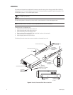
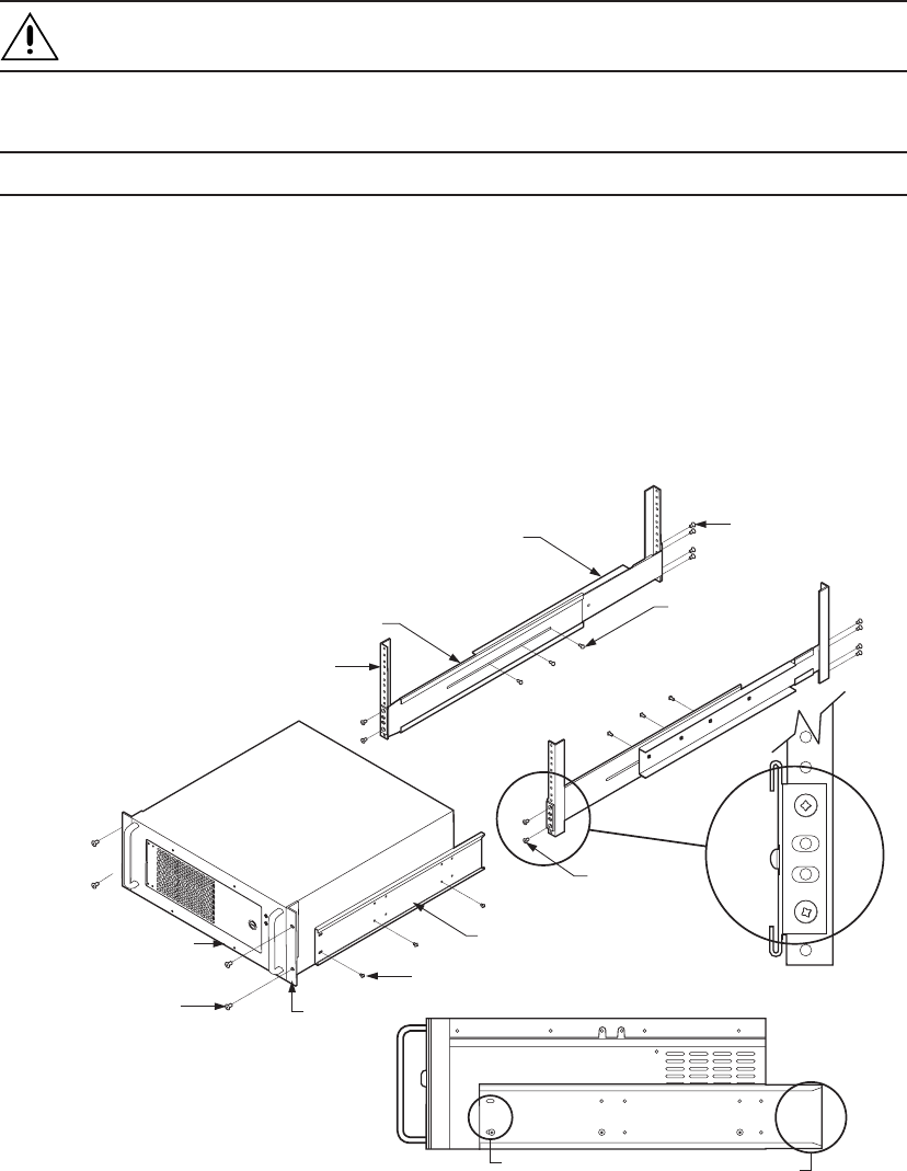
Figure 2. Recorder/Viewstation Rack-Mount Installation
RACK
RECORDER/VIEWSTATION
(6) SCREWS, 8-32 X .250-INCH
PANHEAD (3 EACH SIDE)
(4) SCREWS,
10-32 X .375-INCH
FLAT HEAD
(8) SCREWS,
10-32 X .375-INCH,
FLAT HEAD
BRACKET
(SIDE VIEW)
SLOTTED HOLES
TOWARDSFRONT
OF UNIT
TAPERED ENDS
TOWARDSREAR
OF UNIT
(4) SCREWS,
10-32 X .750-INCH
PHILLIPS, PAN HEAD
WITH WASHERS
REAR MOUNTING RAIL
FRONT MOUNTING RAIL
(6) SCREWS,
8-32 X .375-INCH,
PAN HEADWITH
WASHERS
RACK EAR
MOUNTING
The recorder and viewstation are supplied with the necessary parts for mounting into an industry standard 19-inch (48.26 cm)
wide equipment rack. The recorder should be connected to an uninterruptible power supply (UPS) capable of supplying 2 A for
120 VAC power systems or 1 A for 230 VAC power systems.
CAUTION: The units should be installed in an air-conditioned room where the temperature is maintained between
41° and 86°F (5° and 29°C).
The units can be placed on a flat surface, such as a shelf, or can be installed in a 19-inch wide equipment rack.
NOTE: Allow one rack unit (1.75 inches or 4.5 cm) of space between each unit for air circulation.
To install the units in an equipment rack:
1. Attach the two rack ears to both sides of each unit.
2. Attach the two brackets to both sides of each unit.
3. Attach the mounting rails to the equipment rack.
4. Place the units onto the mounting rails. They should slide in and out of the rack easily.
5. Fasten the rack ears to the equipment rack.
6. Attach the patch panel to the rear of the rack.
The following illustration shows how to mount a recorder or a viewstation into a rack.


