


9
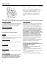
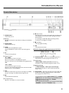
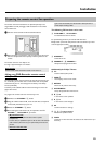
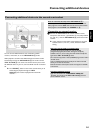
Back of the device
J 4MAINS
Connection to the mains supply (230V/50Hz)
K ANTENNA IN
Connection to the aerial.
L TV OUT
Connection of the aerial cable to the TV.
M EXT2 AUX-I/O
Scart connector to connect an additional device (satellite receiver,
set-top box, video recorder, camcorder, ...). Input for RGB,
S-video signals, input/output for CVBS (video/audio) signals
N EXT1 TO TV-I/O
Scart connector to connect a TV. Output for RGB, S-video signals,
input/output for CVBS (video/audio) signals
O S-VIDEO OUT (Y/C)
S-video (Y/C) connector to connect a S-Video compatible TV
P VIDEO OUT (CVBS)
Yellow cinch socket to connect a TV with video input (CVBS,
Composite Video).
Q AUDIO OUT L/R
White/red cinch socket to connect a TV with audio input sockets
(or an additional device).
R COMPONENT VIDEO OUT
Red/blue/green cinch sockets to connect an additional device with
Component Video input (interlaced, no progressive scan).
S COAX OUT
Cinch connector to connect a digital audio device using a coaxial
cable.
T G-LINK
Connection of the supplied G-LINK™ transmitter to control an
external receiver such as satellite receiver, set-top box, cable TV
box.
U OPTICAL OUT
Optical connector to connect a digital audio device using an
optical cable (Toslink).
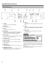
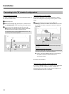
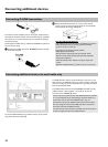
Type plate
Made inHungary
220-240V 50/60Hz 38W
MODEL NO. DVDR 725H/00-02
PROD. NO. _______________________
To identify your DVD-Recorder in case of service queries or if your
machine is stolen, enter the serial number here. The serial number
(PROD. NO.) is printed on the type plate at the back or bottom of the
DVD-recorder.
Please enter the serial number also on the type plate printed on the
last cover page of this user manual.
Introduction to the set