


NAMES AND FUNCTIONS OF PARTS2
10 English
INTRODUCTION
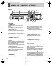
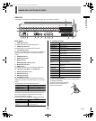
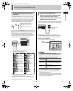
Rear panel
1. VIDEO IN terminals
The DSR-3709 has nine VIDEO IN terminals.
2. VIDEO OUT terminals
The DSR-3709 has nine VIDEO OUT terminals.
3. [ALL RESET] button
When the [ALL RESET] button is pressed, the digital video
recorder is reset and the time is returned to its default
setting.
4. AUDIO IN terminal
5. AUDIO OUT terminal
6. MIC IN terminal
7. MAIN MONITOR output terminal
8. MON2 output terminal
9. USB terminal
This terminal connects to a recordable CD-R/RW drive.
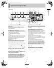
10. LAN terminal (10 Base-T or 100 Base-TX)
11. RS-485 termination switch
12. RS-485 terminal (A)
13. RS-485 terminal (B)
14. ALARM IN terminals
These terminals are used to activate alarm recording in
response to operation of an alarm switch on a connected
device.
The DSR-3709 has nine ALARM IN terminals.
15. SENSOR ALARM OUT terminals
The terminals are used when motion sensors have been
set (JP.81) to output an alarm signal to a connected
device upon detection of motion.
The DSR-3709 has nine SENSOR ALARM OUT terminals.
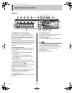
16. CONTROL terminals
17. Power socket (AC IN)
Insert the supplied power cable securely into this socket.
18. Power cord holder
Secure the power cord to the holder
using the cord tie (accessory) as
shown in the illustration.
USB
LAN
TERMINATE
RS-485
OFF ON
A RS-485 B
ALARM IN
AC IN
SENSOR
ALARM OUT
DO NOT CONNECT TO PHONE LINE
C
C
LOCK IN
C
LOCK OUT
ALARM
OUT
ALARM RESET
ALARM FU
LL
NO
N RE
C O
UT
WARNING OUT
FULL
SERIES OU
T
EXIT TIMER IN
SERIES IN
REMOTE
CONTROL
C
123456789
10 11 12 13 14 15 16
C
123456789
10 11 12 13 14 15 16
CR1 R2
1
IN
OUT
ALL
RESET
AUDIO
MONITOR OUT
MON2
MIC IN
IN OUT
2 3 4 5 6 7 8 9 10 11 12 13 14 15
16
MAIN
DSR-3716
(The number of terminals for the DSR-3709 may differ. For more details, see below.)
14
17
18
169 1087654
1
2
13
11
12
3 15
Pin Signal
C Ground
ALARM IN 1 to 16 Alarm input No. 1 through No. 16
Pin Signal
C Ground
SENSOR ALARM OUT
1 to 16
Output of an alarm signal for Camera
No. 1 through No. 16
Pin Signal
C Ground
REMOTE R1 Remote input 1
REMOTE R2 Remote input 2
CLOCK SET IN
Input of a clock setting signal from an
external device
CLOCK SET OUT
Output of a clock setting signal to an
external device
ALARM OUT Total alarm output
ALARM RESET Alarm reset input
WARNING OUT Output of an HDD or FAN malfunction error
FULL
Capacity warning output for normal
recording area space
ALARM FULL
Capacity warning output for alarm recording
area space
SERIES IN
Signal input from an analog series
connection
SERIES OUT Signal output to an analog series connection
EXT TIMER IN Signal input from an external timer
NON REC OUT Non-recording output
C Ground
e00_l8hbg_us_7.book Page 10 Thursday, November 25, 2004 1:44 PM